Infiniti FX35 / FX45. Manual - part 111


  Index      Infiniti     Infiniti FX35 / FX45 (S50) - service repair manual 2008 year


Search            


Content   ..  109  110  111  112   ..


Infiniti FX35 / FX45. Manual - part 111


ATC-40

< SERVICE INFORMATION >

TROUBLE DIAGNOSIS

TJWM0256E
TROUBLE DIAGNOSIS

ATC-41

< SERVICE INFORMATION >

C

D

E

F

G

H

I

K

L

M

A

B

ATC

N

O

P

TJWM0257E

ATC-42

< SERVICE INFORMATION >

TROUBLE DIAGNOSIS

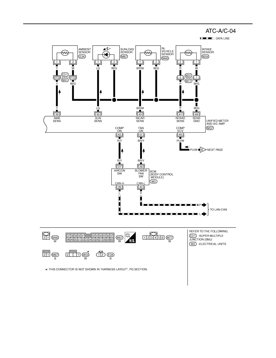
Auto Amp. Terminal and Reference Value

INFOID:0000000001328180

Measure voltage between each terminal and ground by referring ter-
minals and reference value for unified meter and A/C amp.

PIN CONNECTOR TERMINAL LAYOUT

TERMINALS AND REFERENCE VALUE FOR UNIFIED METER AND A/C AMP.

SJIA1566E

RJIA1966E

Terminal 

No.

Wire 

color

Item

Ignition 

switch

Condition

Voltage

(V)

1

L

CAN-H

—

—

—

11

P

CAN-L

—

—

—

21

R/W

Power supply from BAT

OFF

—

Battery voltage

22

W

Power supply from IGN

ON

—

Battery voltage

29

B

Ground (Power)

ON

—

Approx. 0

30

B

Ground

ON

—

Approx. 0

35

LG

Power supply from ACC

ACC

—

Battery voltage

39

Y

Ambient sensor

—

—

—

40

BR/W

In-vehicle sensor

—

—

—

41

P

Intake sensor

—

—

—

42

R/Y

Compressor ON signal

ON

A/C switch: ON
(Blower motor operates.)

Approx. 0

OFF switch: ON
(A/C system: OFF)

SJIA1423J

TROUBLE DIAGNOSIS

ATC-43

< SERVICE INFORMATION >

C

D

E

F

G

H

I

K

L

M

A

B

ATC

N

O

P

Self-Diagnosis Function

INFOID:0000000001328181

DESCRIPTION

The self-diagnosis system diagnoses sensors, door motors, blower motor, etc. by system line. Refer to appli-
cable sections (items) for details. Shifting from normal control to the self-diagnosis system is accomplished by
starting the engine (turning the ignition switch ON) and pressing OFF switch for at least 5 seconds. The OFF
switch must be pressed within 10 seconds after starting the engine (ignition switch is turned ON). This system
will be canceled by either pressing AUTO switch or turning the ignition switch OFF. Shifting from one step is
accomplished by means of pressing temperature control switch (driver side), as required.

43

G/B

A/C LAN signal

ON

—

45

PU/W

ECV (Electric Control Valve) 
signal

ON

Self-diagnosis. STEP-4
(Code No. 45)

46

L/W

Power supply for IGN2

ON

—

Battery voltage

49

W/G

Sensor ground

ON

—

Approx. 0

50

LG

Sunload sensor

—

—

—

53

G

Blower motor control signal

 ON

Blower speed: 1st speed (man-
ual)

54

Y/R

Power supply for each door 
motor

ON

—

Battery voltage

57

BR/Y

Blower motor ON signal

ON

A/C switch: ON 
(Blower motor operates.)

Approx. 0

OFF switch: ON
(A/C system: OFF)

Terminal 

No.

Wire 

color

Item

Ignition 

switch

Condition

Voltage

(V)

SJIA1453J

SJIA1607E

SJIA1454J

SJIA1474J


Content   ..  109  110  111  112   ..