Infiniti FX35 / FX45. Manual - part 107
ATC-24
< SERVICE INFORMATION >
AIR CONDITIONER CONTROL
AIR CONDITIONER CONTROL
Description of Air Conditioner LAN Control System
INFOID:0000000001328167
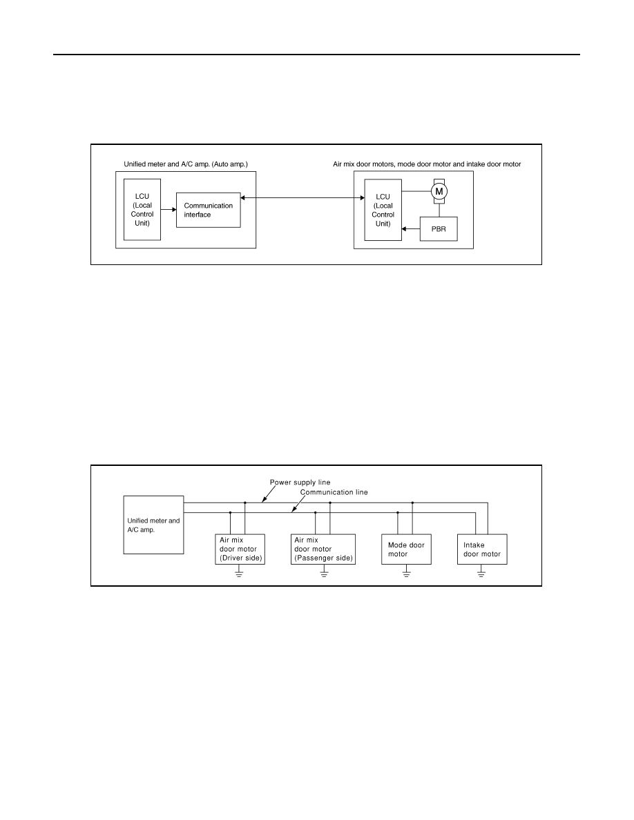
The LAN (Local Area Network) system consists of unified meter and A/C amp., mode door motor, air mix door
motors and intake door motor.
A configuration of these components is shown in the figure below.
System Construction
INFOID:0000000001328168
A small network is constructed between the unified meter and A/C amp., air mix door motors, mode door
motor and intake door motor. The unified meter and A/C amp. and motors are connected by data transmission
lines and motor power supply lines. The LAN network is built through the ground circuits of each door motor.
Addresses, motor opening angle signals, motor stop signals and error checking messages are all transmitted
through the data transmission lines connecting the unified meter and A/C amp. and each door motor.
The following functions are contained in LCUs built into the air mix door motors, the mode door motor and the
intake door motor.
• Address
• Motor opening angle signals
• Data transmission
• Motor stop and drive decision
• Opening angle sensor (PBR function)
• Comparison
• Decision (Unified meter and A/C amp. indicated value and motor opening angle comparison)
OPERATION
The unified meter and A/C amp. receives data from each of the sensors. The unified meter and A/C amp.
sends mode door, air mix door and intake door opening angle data to the mode door motor LCU, air mix door
motor LCU and intake door motor LCU.
The mode door motor, air mix door motors and intake door motor read their respective signals according to the
address signal. Opening angle indication signals received from the unified meter and A/C amp. and each of
the motor position sensors is compared by the LCUs in each door motor with the existing decision and open-
ing angles. Subsequently, HOT/COLD, DEF/VENT and FRE/REC operation is selected. The new selection
data is returned to the unified meter and A/C amp.
SJIA1609E
RJIA1747E