Infiniti FX35 / FX45. Manual - part 21
AT-12
< SERVICE INFORMATION >
A/T FLUID
When wiping away the A/T fluid level gauge, always use lint-free paper, not a cloth one.
e.
Re-insert A/T fluid level gauge into A/T fluid charging pipe as far as it will go.
CAUTION:
To check A/T fluid level, insert the A/T fluid level gauge until the cap contacts the end of the A/T
fluid charging pipe, with the A/T fluid level gauge reversed from the normal attachment conditions.
f.
Remove A/T fluid level gauge and note reading. If reading is at low side of range, add ATF to the A/T fluid
charging pipe.
CAUTION:
Do not overfill.
5.
Drive vehicle for approximately 5 minutes in urban areas.
6.
Make the A/T fluid temperature approximately 65
°
C (149
°
F).
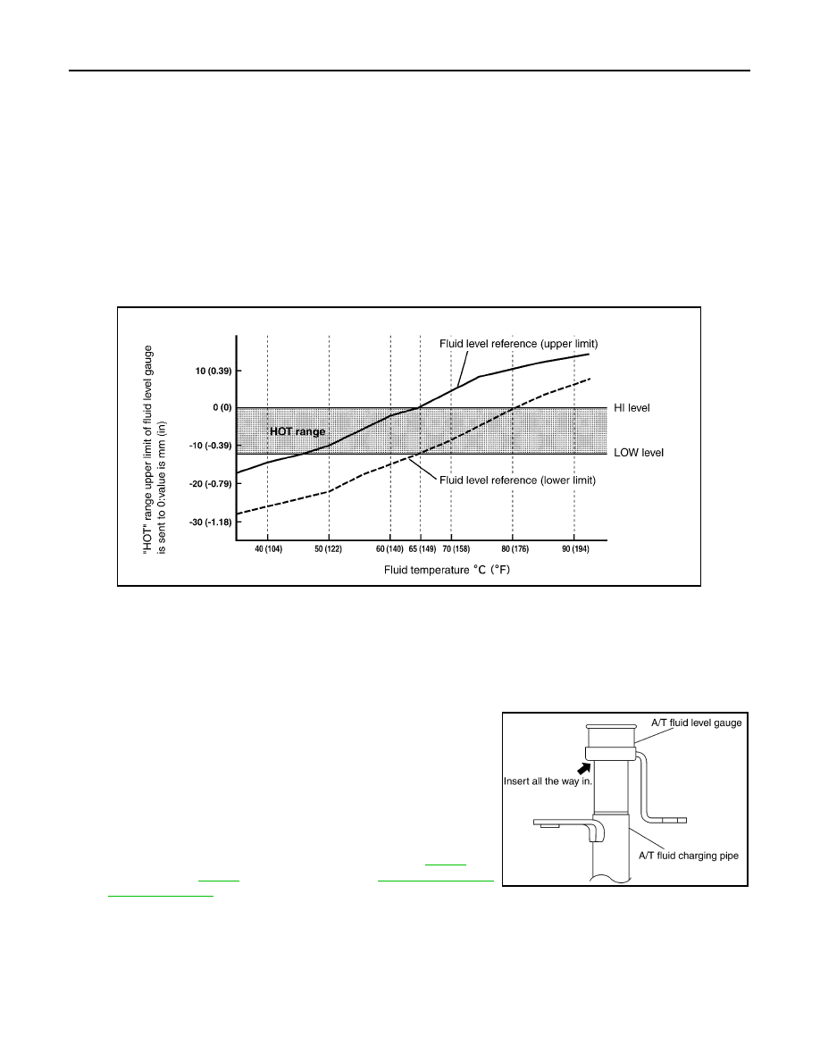
NOTE:
A/T fluid level will be greatly affected by temperature as shown in figure. Therefore, be certain to
perform operation while checking data with CONSULT-III.
a.
Connect CONSULT-III to data link connector.
b.
Select “MAIN SIGNALS” in “DATA MONITOR” mode for “TRANSMISSION” with CONSULT-III.
c.
Read out the value of “ATF TEMP 1”.
7.
Recheck A/T fluid level at A/T fluid temperatures of approximately 65
°
C (149
°
F) using “HOT” range on A/
T fluid level gauge.
CAUTION:
• When wiping away the A/T fluid level gauge, always use lint-free paper, not a cloth one.
• To check A/T fluid level, insert the A/T fluid level gauge
until the cap contacts the end of the A/T fluid charging
pipe, with the A/T fluid level gauge reversed from the nor-
mal attachment conditions as shown.
8.
Check A/T fluid condition.
• If ATF is very dark or smells burned, check operation of A/T.
Flush cooling system after repair of A/T.
• If ATF contains frictional material (clutches, bands, etc.),
replace radiator and flush cooler line using cleaning solvent
and compressed air after repair of A/T. Refer to
VQ35DE) or
(for VK45DE) and
SLIA0016E
SCIA2899E