Infiniti FX35 / FX45. Manual - part 17


  Index      Infiniti     Infiniti FX35 / FX45 (S50) - service repair manual 2008 year


Search            


Content   ..  15  16  17  18   ..


Infiniti FX35 / FX45. Manual - part 17


ACS-62

< SERVICE INFORMATION >

[ICC]

TROUBLE DIAGNOSIS FOR SYMPTOMS
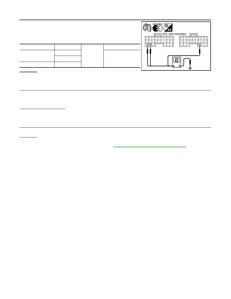
1.

Turn ignition switch OFF.

2.

Disconnect ICC unit connector.

3.

Check continuity between ICC unit harness connector and
ground.

OK or NG

OK

>> GO TO 9.

NG

>> Repair ICC unit ground harness.

9.

CHECK DISPLAYS

1.

Connect ICC unit connector.

2.

Turn ignition switch ON.

3.

Check if all displays illuminate.

Do all displays illuminate?

YES

>> Perform self-diagnosis again.

NO

>> GO TO 10.

10.

CHECK CAN COMMUNICATION

Perform self-diagnosis with CONSULT-III, and check CAN communication system for malfunction.

OK or NG

OK

>> Replace combination meter.

NG

>> CAN communication inspection. Refer to 

ACS-36, "DTC 20 CAN COMM CIRCUIT"

.

ICC unit connector

Terminal

Ground

Continuity

M88

19

Yes

20

M89

46

SKIA6650E

ELECTRICAL COMPONENT INSPECTION

ACS-63

< SERVICE INFORMATION >

[ICC]

C

D

E

F

G

H

I

J

L

M

A

B

ACS

N

O

P

ELECTRICAL COMPONENT INSPECTION

ICC Steering Switch

INFOID:0000000001328857

1.

Disconnect ICC steering switch.

2.

Check resistance between ICC steering switch connector termi-
nals by pressing each switch.

Booster Solenoid

INFOID:0000000001328858

Disconnect booster solenoid/release switch connector, and measure
resistance between terminals 4 and 6.

Release Switch

INFOID:0000000001328859

Disconnect booster solenoid/release switch connector and check
resistance between the terminals.

NOTE:

If pedal is depressed insufficiently, resistance value may remain unchanged.

Terminals

Switch

Condition

Resistance [k

]

14

15

MAIN

Pressed

Approx. 0

Released

Approx. 5.5

CANCEL

Pressed

Approx. 0.3

Released

Approx. 5.5

DISTANCE

Pressed

Approx. 0.7

Released

Approx. 5.5

SET/COAST

Pressed

Approx. 1.4

Released

Approx. 5.5

RESUME/ACCELERATE 

Pressed

Approx. 2.6

Released

Approx. 5.5

PKIB4169E

Terminals

Resistance [

]

4

6

Approx. 1.4 

PKIC5181E

Condition

1 - 3

1 - 2

2 - 3

Release
the brake pedal.

Continuity should 

exist.

Continuity should 

not exist.

Continuity should 

not exist.

Depress
the brake pedal.

Continuity should 

not exist. (Note)

Continuity should 

exist. (Note)

Continuity should 

not exist.

SKIA1256E

ACS-64

< SERVICE INFORMATION >

[ICC]

ELECTRICAL COMPONENT INSPECTION

ICC Brake Switch and Stop Lamp Switch

INFOID:0000000001328860

Check each switch after adjusting brake pedal, refer to 

BR-5

.

ICC Brake Hold Relay

INFOID:0000000001328861

Disconnect ICC brake hold relay, and check continuity between ter-
minals.

Condition

Continuity

ICC brake switch

Stop lamp switch

When brake pedal is depressed

No

Yes

When brake pedal is released

Yes

No

SKIA5984E

Terminals

Condition

Continuity

3

4

Applying battery voltage to be-

tween terminals 1 and 2.

No

6

7

Yes

3

4

No battery voltage

Yes

6

7

No

PKIC4924E

REMOVAL AND INSTALLATION

ACS-65

< SERVICE INFORMATION >

[ICC]

C

D

E

F

G

H

I

J

L

M

A

B

ACS

N

O

P

REMOVAL AND INSTALLATION

ICC Unit

INFOID:0000000001328862

REMOVAL

1.

Remove the instrument passenger lower panel. Refer to 

IP-11, "Removal and Installation"

.

2.

Remove the ECM.

3.

Disconnect ICC unit connector.

4.

Remove a mounting bolt and a nut from ICC unit.

INSTALLATION

Installation is the reverse order of removal.

ICC Sensor

INFOID:0000000001328863

REMOVAL

1.

Remove the front bumper. Refer to 

EI-15, "Removal and Installation"

.

2.

Disconnect ICC sensor connector.

3.

Remove mounting bolts from ICC sensor.

INSTALLATION

Installation is the reverse order of removal.

SKIA5985E

SKIA5986E


Content   ..  15  16  17  18   ..