Infiniti FX35, FX50 (S51). Manual - part 767
MULTIPORT FUEL INJECTION SYSTEM
EC-609
< SYSTEM DESCRIPTION >
[VK50VE]
C
D
E
F
G
H
I
J
K
L
M
A
EC
N
P
O
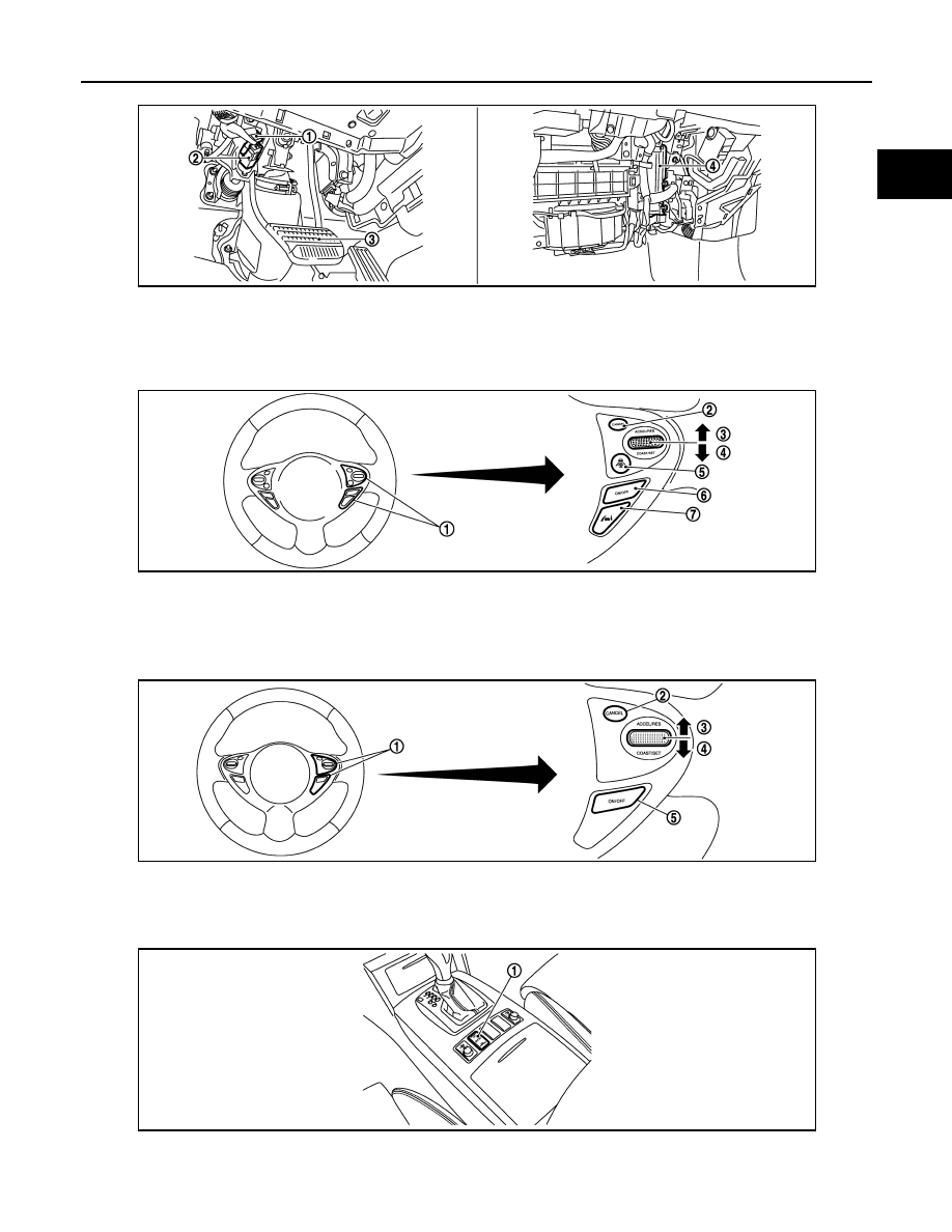
1.
Stop lamp switch
2.
ASCD brake switch (ASCD models)
ICC brake switch (ICC models)
3.
Brake pedal
4.
ECM
1.
ICC steering switch
2.
CANCEL switch
3.
RESUME/ACCELERATE switch
4.
SET/COAST switch
5.
DISTANCE switch
6.
MAIN switch
7.
LDP switch
1.
ASCD steering switch
2.
CANCEL switch
3.
RESUME/ACCELERATE switch
4.
SET/COAST switch
5.
MAIN switch
1.
Snow mode switch
JMBIA1509ZZ
JMBIA1507ZZ
JMBIA1508ZZ
JMBIA1623ZZ