Infiniti FX35, FX50 (S51). Manual - part 734
ICC BRAKE SWITCH
EC-477
< DTC/CIRCUIT DIAGNOSIS >
[VQ35HR]
C
D
E
F
G
H
I
J
K
L
M
A
EC
N
P
O
Is the inspection result normal?
YES
>> INSPECTION END
NO
>> GO TO 3.
3.
CHECK ICC BRAKE SWITCH POWER SUPPLY CIRCUIT-I
1.
Turn ignition switch OFF.
2.
Disconnect ICC brake switch harness connector.
3.
Turn ignition switch ON.
4.
Check the voltage between ICC brake switch harness connector and ground.
Is the inspection result normal?
YES
>> GO TO 10.
NO
>> GO TO 4.
4.
CHECK ICC BRAKE SWITCH POWER SUPPLY CIRCUIT-II
1.
Turn ignition switch OFF.
2.
Disconnect ICC brake hold relay.
3.
Turn ignition switch ON.
4.
Check the voltage between ICC brake hold relay harness connector and ground.
Is the inspection result normal?
YES
>> GO TO 6.
NO
>> GO TO 5.
5.
DETECT MALFUNCTIONING PART
Check the following.
• Fuse block (J/B) connector E103
• 10 A fuse (No. 3)
• Harness for open or short between ICC brake hold relay and fuse
>> Repair open circuit or short to ground in harness or connectors.
6.
CHECK ICC BRAKE SWITCH POWER SUPPLY CIRCUIT-III
1.
Turn ignition switch OFF.
2.
Check the continuity between ICC brake switch harness connector and ICC brake hold relay harness con-
nector.
3.
Also check harness for short to ground and short to power.
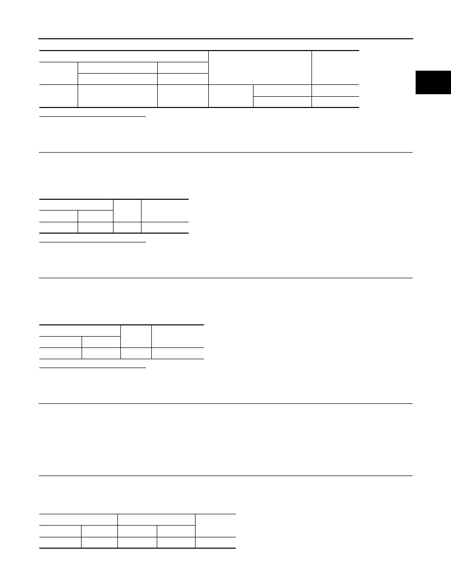
ECM
Condition
Voltage (V)
Connector
+
–
Terminal
Terminal
M107
117
(ICC brake switch signal)
128
Brake pedal
Slightly depressed
Approx. 0
Fully released
Battery voltage
ICC brake switch
Ground
Voltage
Connector
Terminal
E114
1
Ground
Battery voltage
ICC brake hold relay
Ground
Voltage
Connector
Terminal
E91
3
Ground
Battery voltage
ICC brake switch
ICC brake hold relay
Continuity
Connector
Terminal
Connector
Terminal
E114
1
E91
4
Existed