Infiniti FX35, FX50 (S51). Manual - part 313
CCS-72
< DTC/CIRCUIT DIAGNOSIS >
[ICC (FULL SPEED RANGE)]
C1A09 BOOSTER SOLENOID
4.
Check for continuity between brake booster control unit harness connector and ground.
Is the inspection result normal?
YES
>> GO TO 4.
NO
>> Repair the harnesses or connectors.
4.
CHECK BOOSTER SOLENOID
Check the booster solenoid. Refer to
CCS-72, "Component Inspection"
.
Is the inspection result normal?
YES
>> Replace the brake booster control unit.
NO
>> Replace the brake booster.
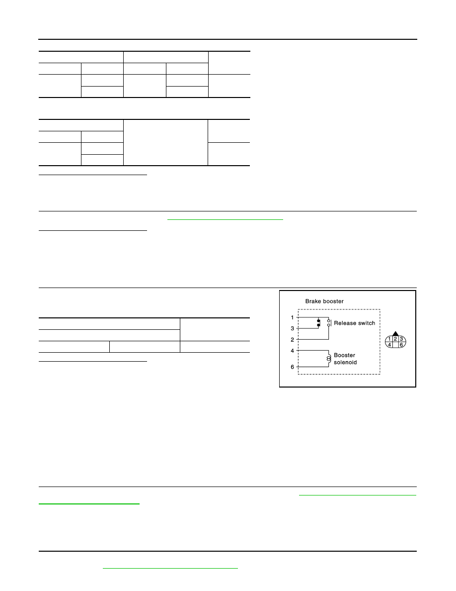
Component Inspection
INFOID:0000000005501607
1.
CHECK BRAKE BOOSTER (BOOSTER SOLENOID)
Check resistance between brake booster (booster solenoid) termi-
nals.
Is the inspection result normal?
YES
>> INSPECTION END
NO
>> Replace the brake booster.
Special Repair Requirement
INFOID:0000000005501608
DESCRIPTION
Perform the action test after adjusting the laser beam aiming of ICC sensor integrated unit when the following
operation is performed.
• Removal and installation of ICC sensor integrated unit
• Replacement of ICC sensor integrated unit
SPECIAL REPAIR REQUIREMENT
1.
LASER BEAM AIMING ADJUSTMENT OF ICC SENSOR INTEGRATED UNIT
Adjust the laser beam aiming of the ICC sensor integrated unit. Refer to
>> GO TO 2.
2.
CHECK ICC SYSTEM
1.
Erase the “Self Diagnostic Result”, and then perform “All DTC Reading” again after performing the action
test. (Refer to
CCS-18, "ACTION TEST : Description"
Brake booster control unit
Brake booster
Continuity
Connector
Terminal
Connector
Terminal
B250
10
E44
4
Existed
12
6
Brake booster control unit
Ground
Continuity
Connector
Terminal
B250
10
Not existed
12
Brake booster
Resistance
Terminal
4
6
Approx. 1.4
Ω
JPOIA0160GB