Infiniti FX35, FX50 (S51). Manual - part 299


  Index      Infiniti     Infiniti FX35, FX50 (S51) - service repair manual 2010 year


Search            


Content   ..  297  298  299  300   ..


Infiniti FX35, FX50 (S51). Manual - part 299


CCS-16

< BASIC INSPECTION >

[ICC (FULL SPEED RANGE)]

INSPECTION AND ADJUSTMENT

3.

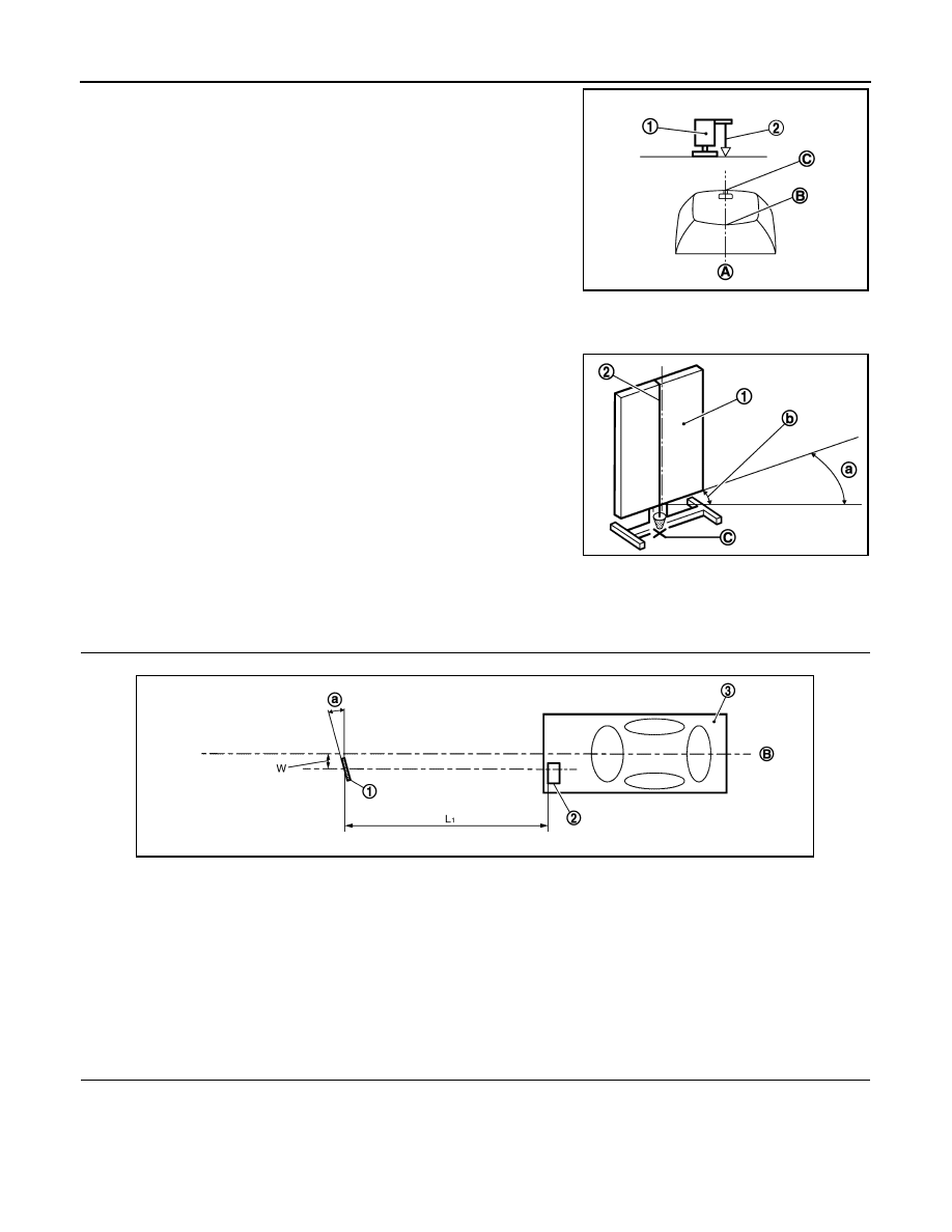
Adjust the position of the ICC target board (1) so that the
extended line (A) that links the center of the rear window glass
(the center of the rear window defogger pattern) (B) and the cen-
ter of the windshield (the setting part of the room mirror) (C)
align with the weight suspended (2) from the ICC target board.

4.

Remove the thread suspended to the right side of ICC target board and suspend a thread with weight on
tip on the center of the ICC target board. Then mark the point of weight on the ground.

5.

Pivot the edge of the ICC target board 25

°

 (a) to either side.

NOTE:
Approx. 90 mm (3.54 in) (b) shift rates the 25

°

 (a) movement.

>> GO TO 4.

4.

CHECK THE ICC TARGET BOARD INSTALLATION POSITION

Check that the ICC target board (1) is located as shown in the figure. 

NOTE:
The distance between laser beam axis and ICC target board is 4.0 m (13.0 ft). 

>> GO TO 5.

5.

CHECK THE ICC TARGET BOARD INSTALLATION AREA

JSOIA0025ZZ

1

: ICC target board

2

: String with a weight

C

: ICC target board center marking point

JSOIA0026ZZ

1.

ICC target board

2.

ICC sensor integrated unit

3.

Vehicle

B.

Vehicle center

L

1

.

4.0 m (13.0 ft)

W.

315 mm (12.4 in)

a.

25

°

JSOIA0017ZZ

CCS

INSPECTION AND ADJUSTMENT

CCS-17

< BASIC INSPECTION >

[ICC (FULL SPEED RANGE)]

C

D

E

F

G

H

I

J

K

L

M

B

N

P

A

Do not place anything other than ICC target board in the space shown in the figure (view from top). 

NOTE:
In case the space shown in the figure is not available, cover the side of the ICC target board with a 1400
mm(4.6 ft)-size frosted black board or black cloth.

>> Go to 

CCS-17, "LASER BEAM AIMING ADJUSTMENT : Special Repair Requirement (Laser

Beam Aiming Adjustment)"

LASER BEAM AIMING ADJUSTMENT : Special Repair Requirement (Laser Beam 
Aiming Adjustment)

INFOID:0000000005501555

DESCRIPTION

• Adjust the laser beam aiming in a vertical direction with CONSULT-III as per the following. 
• The laser beam aiming adjustment in a horizontal direction is performed automatically with CONSULT-III. 

CAUTION:

• Never look directly into the laser beam source (ICC sensor integrated unit body window) during laser

beam aiming adjustment. 

• Perform all necessary work for laser beam aiming adjustment until the adjustment completes as

shown in the procedure. If the procedure does not complete, the ICC system is inoperable.

1.

SET CONSULT-III TO THE LASER BEAM AIMING ADJUSTMENT MODE

1.

Start the engine.

2.

Connect CONSULT-III and select “Work support” of “ICC”. 

3.

Select “LASER BEAM ADJUST” after the “Work support” screen is displayed. 

4.

Select “START” after the “LASER BEAM ADJUST” screen is displayed. 
NOTE:
If the adjustment screen does not appear within approximately 10 seconds after “LASER BEAM ADJUST”
is selected, the following causes are possible. 
• The ICC target board is not installed in the correct position. 
• Adequate space is not secured around the ICC target board. 
• The laser beam aiming adjustment exceeds its proper installation range. 
- Deformation of vehicle body.
- Deformation of unit.
- Deformation of bracket.
• The area is not suitable for the adjustment work.
• ICC sensor integrated unit body window is not clean. 
• The ICC system warning lamp illuminates. 

>> GO TO 2.

2.

LASER BEAM AIMING ADJUSTMENT

After “ADJUST THE VERTICAL OF LASER BEAM AIMING” is displayed on CONSULT-III screen, adjust by
turning the up-down direction adjusting screw until “U/D CORRECT” becomes 

±

4 or less. 

NOTE:

1.

ICC target board

2.

ICC sensor integrated unit

L

1

.

6.5  m  (21.3  ft)

L

2

.

4.0 m (13.0 ft)

W.

3.5 m (11.5 ft)

JSOIA0027ZZ

CCS-18

< BASIC INSPECTION >

[ICC (FULL SPEED RANGE)]

INSPECTION AND ADJUSTMENT

• Turn the up-down direction adjusting screw slowly. The value change on display is slower than actual move-

ment of the ICC sensor integrated unit. Wait for 2 seconds every time the up-down direction adjusting screw
is turned half a rotation.

• Turning the up-down direction adjusting screw (A) clockwise

directs the laser beam downward (B). The laser beam directs
upward (C) when turning up-down direction adjusting screw coun-
terclockwise.

CAUTION:

Be careful not to cover the ICC sensor integrated unit body win-
dow with a hand or the other part of body of worker during
adjustment. 

>> GO TO 3.

3.

LASER BEAM AIMING CONFIRMATION

1.

When the “U/D CORRECT” value becomes 

±

4 or less, check that no value greater than 

±

4 appears when

the vehicle is left with no load on the ICC sensor integrated unit (hand removed) for at least 2 seconds. 

2.

When “COMPLETED THE VERTICAL AIMING OF LASER BEAM” display appears, touch “END”. 

CAUTION:

Always check that the value of “U/D CORRECT” remains 

±

4 or less when the ICC sensor inte-

grated unit is left alone for at least 2 seconds.

3.

Check that “ADJUSTING AUTOMATIC HORIZONTAL LASER BEAM AIMING” is displayed and wait for a
short period of time. (The maximum: Approx 10 seconds).

4.

Check that “Normally Completed” is displayed, and select “End” to end “LASER BEAM ADJUST”. 

CAUTION:

Once “LASER BEAM ADJUST” is started with CONSULT-III, always continue the work until the
horizontal laser beam aiming adjustment is completed successfully. If the job is stopped midway,
the laser beam aiming is not adjusted and the ICC system cannot operate. 

>> LASER BEAM AIMING ADJUSTMENT END

ACTION TEST

ACTION TEST : Description

INFOID:0000000005501556

Always perform the ICC system action test to check that the ICC system operates normally after replacing the
ICC sensor integrated unit or repairing any ICC system malfunction. 

CAUTION:

• Always drive safely when performing the action test. 
• Turn the DCA system to OFF when performing the action test.

ACTION TEST : Special Repair Requirement (Vehicle-To-Vehicle Distance Control 
Mode)

INFOID:0000000005501557

NOTE:
• When there is no vehicle ahead, drive at the set speed steadily.
• When there is a vehicle ahead, control to maintain distance from the vehicle ahead, watching its speed.
• The running speed can be set between 32 km/h (20 MPH) and 144 km/h (90 MPH).

CAUTION:

Never set the cruise speed exceeding the posted speed limit.

1.

CHECK FOR MAIN SWITCH

1.

Start the engine.

JPOIA0136ZZ

CCS

INSPECTION AND ADJUSTMENT

CCS-19

< BASIC INSPECTION >

[ICC (FULL SPEED RANGE)]

C

D

E

F

G

H

I

J

K

L

M

B

N

P

A

2.

Press the MAIN switch (1) (less than 1.5 seconds). 

3.

Check the ICC system display on the information display to check that the vehicle-to-vehicle distance con-
trol mode is ready for activation.

4.

Press the MAIN switch, and check that the ICC system display on the information display turns OFF when
the ICC system is deactivated.

5.

Check that the ICC system display on the information display turns OFF after starting the engine again. 

>> GO TO 2.

2.

CHECK FOR DISTANCE SWITCH

1.

Start the engine.

2.

Press the MAIN switch (less than 1.5 seconds). 

3.

Press the DISTANCE switch. 

4.

Check that the set distance indicator changes display in order of: (Long)

(Middle)

(Short).

NOTE:
When the MAIN switch is turned ON, initial setting set to (Long). 

>> GO TO 3.

3.

CHECK FOR RESUME/ACCELERATE, SET/COAST, AND CANCEL SWITCHES

1.

Check that RESUME/ACCELERATE, SET/COAST, CANCEL switches are operated smoothly.

2.

Check that switches come up as hand is released from the switches.

>> GO TO 4.

4.

SET CHECKING (1)

1.

Start the engine.

2.

Press the MAIN switch (less than 1.5 seconds) and turn the vehicle-to-vehicle distance control mode ON. 

3.

Drive the vehicle at 32 km/h (20 MPH) or more.

Information display status

MAIN switch indicator (2)

:

ON

Set distance indicator (3)

:

Long mode

Own vehicle indicator (4)

:

ON

Set vehicle speed indicator (5)

:

“— —”
“km/h” (“MPH”)

JSOIA0148ZZ

JPOIA0256GB


Content   ..  297  298  299  300   ..