Infiniti FX35, FX50 (S51). Manual - part 1903


  Index      Infiniti     Infiniti FX35, FX50 (S51) - service repair manual 2010 year


Search            


Content   ..  1901  1902  1903  1904   ..


Infiniti FX35, FX50 (S51). Manual - part 1903


WCS-32

< DTC/CIRCUIT DIAGNOSIS >

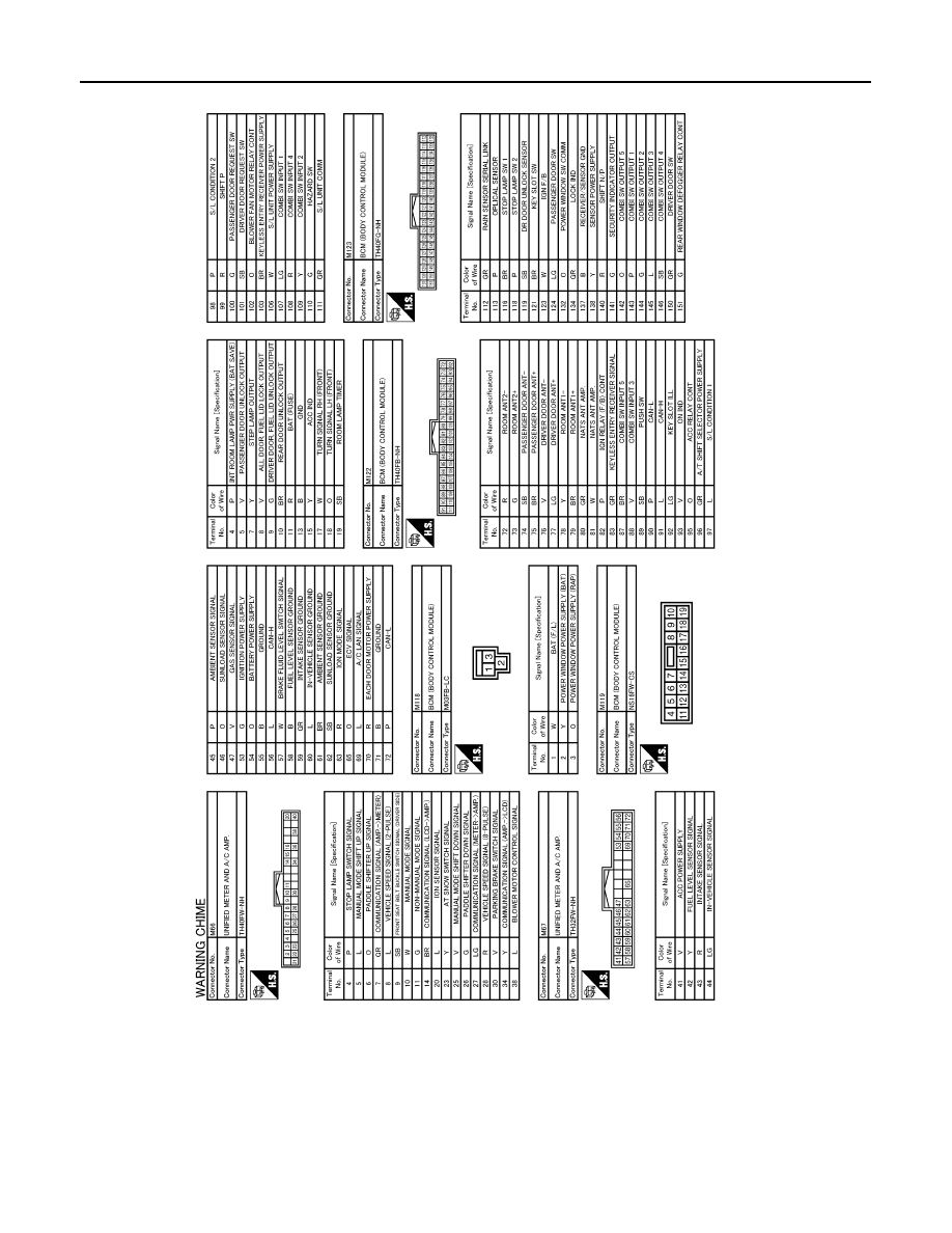
WARNING CHIME SYSTEM

JCNWA2830GB

WCS

COMBINATION METER

WCS-33

< ECU DIAGNOSIS INFORMATION >

C

D

E

F

G

H

I

J

K

L

M

B

A

O

P

ECU DIAGNOSIS INFORMATION

COMBINATION METER

Reference Value

INFOID:0000000005524755

VALUES ON THE DIAGNOSIS TOOL

Refer to 

WCS-53, "Reference Value"

.

TERMINAL LAYOUT

PHYSICAL VALUES

JPNIA1324ZZ

Terminal No.

(Wire color)

Description

Condition

Value

(Approx.)

+

Signal name

Input/

Output

1

(O)

Ground

Battery power supply

Input

Ignition 
switch 
OFF

Battery voltage

2

(LG)

Ground

Communication signal 
(METER

 AMP.)

Output

Ignition 
switch 
ON

3

(GR)

Ground

Communication signal 
(AMP.

 METER)

Input

Ignition 
switch 
ON

5

(B)

Ground

Ground

Ignition 
switch 
ON

0  V

6

(W)

Ground

Alternator signal

Input

Ignition 
switch 
ON

Charge warning lamp ON

0 V

Charge warning lamp OFF

Battery voltage

7

(P)

Ground

Air bag signal

Input

Ignition 
switch 
ON

Air bag warning lamp ON

4 V

Air bag warning lamp OFF

0 V

10

(G)

Ground

Security indicator signal

Input

Ignition 
switch 
OFF

Security warning lamp ON

0 V

Security warning lamp OFF

12 V

JSNIA0027GB

JSNIA0027GB

WCS-34

< ECU DIAGNOSIS INFORMATION >

COMBINATION METER

15

(B)

Ground

Ground

Ignition 
switch 
ON

0  V

16

(B)

Ground

Meter control switch ground

Ignition 
switch 
ON

0  V

21

(R)

Ground

Ignition signal

Input

Ignition 
switch 
ON

Battery voltage

22

(B)

Ground

Ground

Ignition 
switch 
ON

0  V

24

(BR)

Ground

Communication signal 
(LCD

 AMP.)

Output

Ignition 
switch 
ON

25

(Y)

Ground

Communication signal 
(AMP.

 LCD)

Input

Ignition 
switch 
ON

26

(R)

Ground

Vehicle speed signal
(8-pulse)

Input

Ignition 
switch 
ON

Speedometer operated
[When vehicle speed is ap-
prox. 40 km/h (25 MPH)]

NOTE:
The maximum voltage varies de-
pending on the specification 
(destination unit).

27

(V)

Ground

Parking brake switch signal

Input

Ignition 
switch 
ON

Parking brake ON

0 V

Parking brake OFF

28

(W)

Ground

Brake fluid level switch sig-
nal

Input

Ignition 
switch 
ON

Brake fluid level is normal.

5 V

The brake fluid level is low-
er than the low level

0 V

Terminal No.

(Wire color)

Description

Condition

Value

(Approx.)

+

Signal name

Input/

Output

JSNIA0028GB

JSNIA0027GB

JSNIA0012GB

JSNIA0007GB

WCS

COMBINATION METER

WCS-35

< ECU DIAGNOSIS INFORMATION >

C

D

E

F

G

H

I

J

K

L

M

B

A

O

P

29

(SB)

Ground

Seat belt buckle switch sig-
nal (driver side)

Input

Ignition 
switch 
ON

When driver seat belt is fas-
tened

12 V

When driver seat belt is un-
fastened

0 V

30

(G)

Ground

Passenger seat belt warn-
ing signal

Input

Ignition 
switch 
ON

• When getting in the pas-

senger seat

• When passenger seat 

belt is fastened

12 V

• When getting in the pas-

senger seat

• When passenger seat 

belt is unfastened

0 V

31

(L)

Ground

Washer level switch signal

Input

Ignition 
switch 
ON

Washer level switch ON

0 V

Washer level switch OFF

5 V

34

(O)

Ground

Illumination control signal

Output

Ignition 
switch 
ON

Lighting switch ON, then 
operate the illumination 
control switch.

NOTE:
When brightness level is midway

36

(LG)

16

(B)

Select switch signal

Input

Ignition 
switch 
ON

When  

is 

pressed

0 V

Other than the above

5 V

37

(SB)

16

(B)

Enter switch signal

Input

Ignition 
switch 
ON

When 

 is pressed

0 V

Other than the above

5 V

38

(L)

16

(B)

Trip A/B reset switch signal

Input

Ignition 
switch 
ON

When trip A/B reset switch 
is pressed

0 V

Other than the above

5 V

39

(P)

16

(B)

Illumination control switch 
signal (–)

Input

Ignition 
switch 
ON

When 

 switch is 

pressed

0 V

Other than the above

5 V

40

(O)

16

(B)

Illumination control switch 
signal (+)

Input

Ignition 
switch 
ON

When  

switch 

is 

pressed

0 V

Other than the above

5 V

Terminal No.

(Wire color)

Description

Condition

Value

(Approx.)

+

Signal name

Input/

Output

JSNIA0010GB


Content   ..  1901  1902  1903  1904   ..