Content .. 1776 1777 1778 1779 ..
Infiniti FX35, FX50 (S51). Manual - part 1778
C1911, C1912 RAS MOTOR POWER SUPPLY
STC-53
< DTC/CIRCUIT DIAGNOSIS >
[WITH REAR ACTIVE STEER]
C
D
E
F
H
I
J
K
L
M
A
B
STC
N
O
P
• Open between the ignition switch and RAS control unit harness connector No. 27 terminal
• Ignition switch
2.
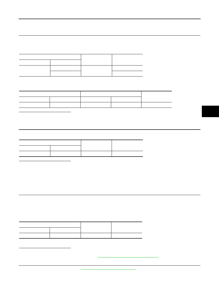
CHECK RAS MOTOR POWER SUPPLY CIRCUIT (1)
1.
Turn the ignition switch OFF.
2.
Remove RAS motor relay.
3.
Check the continuity between RAS motor relay harness connector and ground.
4.
Check the continuity between RAS motor relay harness connector and RAS control unit harness connec-
tor.
Is the inspection result normal?
YES
>> GO TO 3.
NO
>> Repair or replace the harnesses and connectors.
3.
CHECK RAS MOTOR POWER SUPPLY CIRCUIT (2)
Check the voltage between RAS motor relay harness connector and ground.
Is the inspection result normal?
YES
>> GO TO 4.
NO
>>
Check the following items. Repair or replace the malfunctioning parts.
• 20A fuse (#37) open
- Short among 20A fuse (#37) connector, RAS motor relay harness connector No. 3 terminal and
the ground
• Open between the battery and RAS motor relay harness connector No. 3 terminal
4.
CHECK RAS MOTOR POWER SUPPLY CIRCUIT (3)
1.
Connect RAS control unit harness connector.
2.
Turn the ignition switch ON.
CAUTION:
Never start the engine.
3.
Check the voltage between RAS control unit harness connector and ground.
4.
Turn the ignition switch OFF.
Is the inspection result normal?
YES
>> GO TO 5.
NO
>> Replace RAS control unit. Refer to
STC-109, "Removal and Installation"
5.
CHECK RAS MOTOR RELAY
Check the RAS motor relay. Refer to
STC-54, "Component Inspection"
.
RAS motor relay
—
Continuity
Connector
Terminal
B36
2
Ground
Existed
1 Not
existed
RAS motor relay
RAS control unit
Continuity
Connector
Terminal
Connector
Terminal
B36
1
B37
25
Existed
RAS motor relay
—
Voltage (Approx.)
Connector
Terminal
B36
3
Ground
Battery voltage
RAS control unit
—
Voltage (Approx.)
Connector
Terminal
B37
25
Ground
Battery voltage