Content .. 1552 1553 1554 1555 ..
Infiniti FX35, FX50 (S51). Manual - part 1554
REAR DRIVE SHAFT
RAX-13
< REMOVAL AND INSTALLATION >
C
E
F
G
H
I
J
K
L
M
A
B
RAX
N
O
P
9.
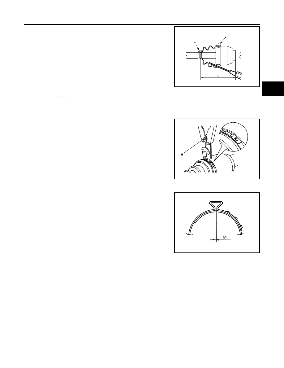
Install the boot securely into grooves (indicated by “*” marks)
shown in the figure.
CAUTION:
If grease adheres to the boot mounting surface (indicated
by “*” mark) on the shaft or housing, boot may come off.
Remove all grease from the surfaces.
10. To prevent the deformation of the boot, adjust the boot installa-
tion length (L) to the specified value shown below by inserting
the suitable tool into inside of the boot from the large diameter
side of boot and discharging the inside air.
CAUTION:
• If the boot installation length is outside the standard, it may cause breakage of boot.
• Be careful not to touch the inside of the boot with the tip of tool.
11. Secure the ends of the boot with boot bands using the boot band
crimping tool (A) [SST: KV40107300 (
−
)].
CAUTION:
Never reuse boot band.
NOTE:
Secure boot band so that dimension (M) meets the specification
as shown in the figure.
12. Secure joint sub-assembly and shaft, and then make sure that
they are in the correct position when rotating boot. Install them
with boot band when boot installation positions become incor-
rect.
CAUTION:
Never reuse boot band.
13. Install dust shield to drive shaft.
CAUTION:
Never reuse dust shield.
FINAL DRIVE SIDE
FINAL DRIVE SIDE : Disassembly and Assembly
INFOID:0000000005249014
DISASSEMBLY
1.
Fix shaft with a vise.
CAUTION:
Protect shaft when fixing with a vise using aluminum or copper plates.
2.
Remove boot bands, and then remove boot from housing.
3.
Put matching marks on housing and shaft.
CAUTION:
Use paint or similar substance for matching marks. Never scratch the surface.
L
: Refer to
JPDIF0018ZZ
PDIA1187J
M
: 1.0 – 4.0 mm (0.039 – 0.157 in)
DSF0047D