Content .. 1243 1244 1245 1246 ..
Infiniti FX35, FX50 (S51). Manual - part 1245
INL-180
< SYMPTOM DIAGNOSIS >
INTERIOR LIGHTING SYSTEM SYMPTOMS
SYMPTOM DIAGNOSIS
INTERIOR LIGHTING SYSTEM SYMPTOMS
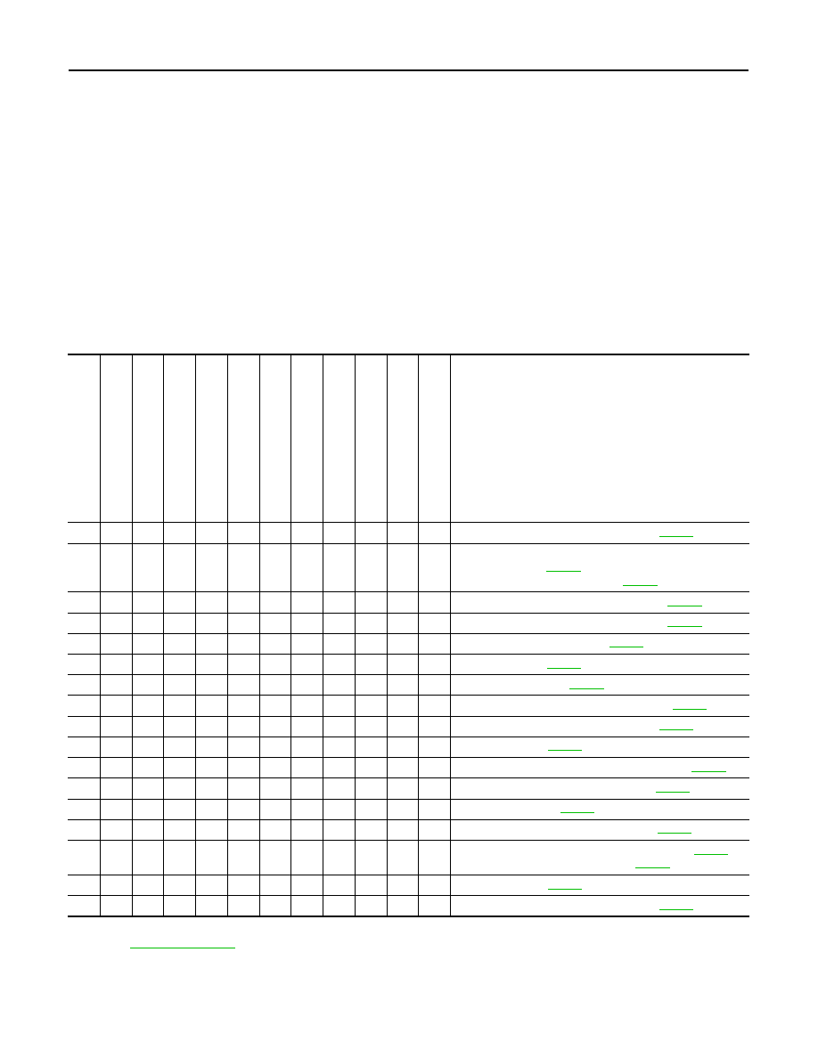
Symptom Table
INFOID:0000000005245623
CAUTION:
Perform the self-diagnosis with CONSULT-III before the symptom diagnosis. Perform the trouble diag-
nosis if any DTC are detected.
SYMPTOMS BY ITEM
1.
Identify the malfunctioning by checking each lamp (whether it can turn ON or not).
2.
Check the malfunction combinations.
3.
Identify the malfunctioning part from the agreed combination and repair or replace the part.
NOTE:
When a lamp other than those in the following table is not turned ON/OFF, check the bulb, the lamp housing,
and the direct circuit.
Malfunction item:
×
*1: Map lamp main switch ALL ON or DOOR
*2: Refer to
for linked illuminations.
Ma
p l
am
p
s
*1
Pers
on
al
l
a
mp
s
*1
Ce
nt
er c
o
n
s
o
le
ind
ire
ct
ill
um
in
ati
o
n
V
a
nit
y
mirror lamp
Foo
t l
a
mp
s
Pu
sh
-bu
tton
i
gni
tio
n
sw
itch
il
lu
m
in
a
ti
on
Mo
od
la
mp
(Rea
r d
o
o
r arm
res
t)
Pu
dd
le la
mp
s
Mo
od
la
mp
(F
ront
do
or
arm
res
t)
Il
lum
in
a
tion
s
*2
(L
in
ke
d wi
th
ho
sp
it
a
lit
y l
ig
h
ti
ng
)
St
e
p
l
a
m
p
s
Lu
gg
ag
e ro
om
la
mp
s
Inspection item (Reference)
×
×
×
×
×
×
×
×
×
×
×
×
Interior room lamp power supply circuit (
×
×
×
×
×
×
×
×
×
×
1.
Power supply and ground circuit of total illumination
control unit (
2.
Battery saver signal circuit (
×
×
×
×
×
×
×
Hospitality lighting power supply 1 circuit (
×
×
Hospitality lighting power supply 2 circuit (
×
×
Map lamp main switch circuit (
×
Map lamp circuit (
)
×
Personal lamp circuit (
×
Center console indirect illumination circuit (
)
×
The lamp housing and the direct circuit (
×
Foot lamp circuit (
×
Push-button ignition switch illumination circuit (
×
Mood lamp (Rear door armrest) circuit (
)
×
Puddle lamp circuit (
×
Mood lamp (Front door armrest) circuit (
)
×
1.
Hospitality lighting power supply 3 circuit (
)
2.
Hospitality illumination circuit (
×
Step lamp circuit (
×
The lamp housing and the direct circuit (