Infiniti EX35. Manual - part 921
HAC-80
< COMPONENT DIAGNOSIS >
[AUTOMATIC AIR CONDITIONER]
BLOWER MOTOR
BLOWER MOTOR
WITHOUT LEFT AND RIGHT VENTILATION TEMPERATURE SEPARATELY
CONTROL SYSTEM
WITHOUT LEFT AND RIGHT VENTILATION TEMPERATURE SEPARATELY CON-
TROL SYSTEM : Description
INFOID:0000000003545615
COMPONENT DESCRIPTION
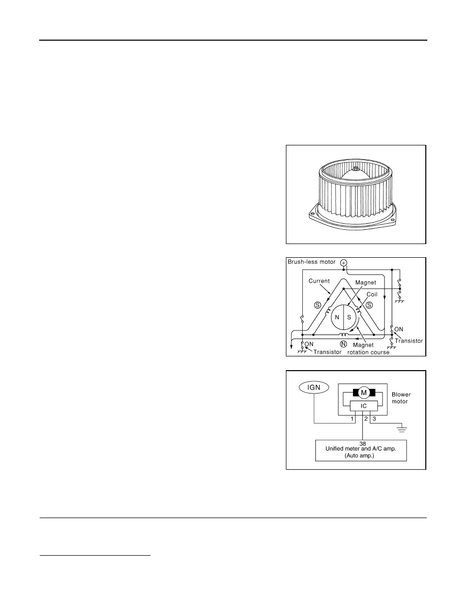
Brush-less Motor
The blower motor utilizes a brush-less motor with a rotating magnet.
Quietness is improved over previous motors where the brush was
the point of contact and the coil rotated.
Blower motor circuit
WITHOUT LEFT AND RIGHT VENTILATION TEMPERATURE SEPARATELY CON-
TROL SYSTEM : Component Function Check
INFOID:0000000003545616
1.
CONFIRM SYMPTOM BY PERFORMING THE FOLLOWING OPERATIONAL CHECK
1.
Turn fan control dial clockwise. Blower should operate on low speed.
2.
Turn fan control dial clockwise, and continue checking blower speed and fan symbol until all speeds
checked.
Is the inspection result normal?
YES
>> END.
RJIA2467J
ZHA152H
RJIA4071E