Infiniti EX35. Manual - part 900
EVAPORATOR
HA-59
< ON-VEHICLE REPAIR >
C
D
E
F
G
H
J
K
L
M
A
B
HA
N
O
P
EVAPORATOR
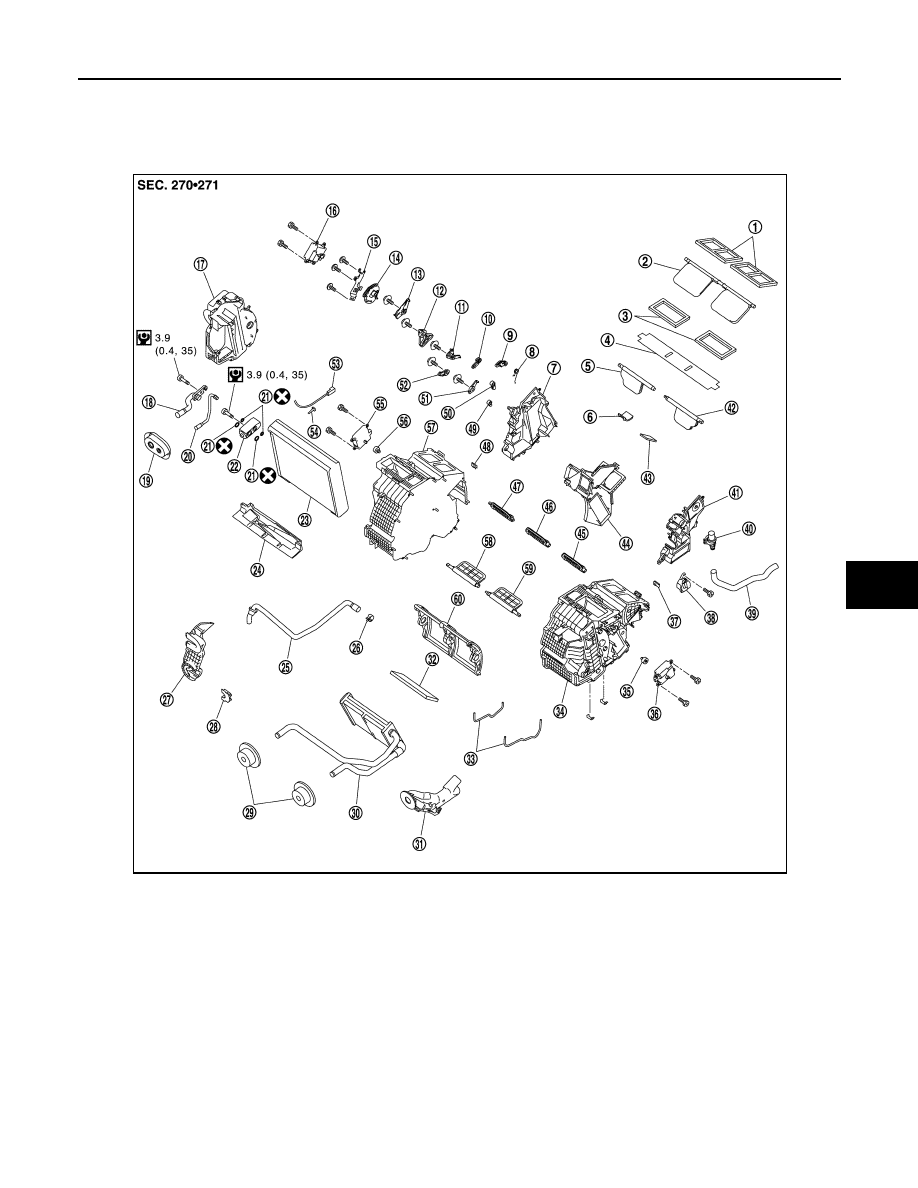
Exploded View
INFOID:0000000003565963
1.
Ventilator seal
2.
Ventilator door
3.
Defroster seal
4.
Packing
5.
Defroster door (right)
6.
Packing
7.
Foot duct (right)
8.
Ventilator door spring
9.
Ventilator door lever
10.
Foot door lever
11.
Foot door link
12. Main link sub
13.
Ventilator door link
14.
Main link
15. Mode door motor bracket
16.
Mode door motor
17.
Evaporator cover
18. Low-pressure pipe 1
19.
Cooler pipe grommet
20.
High-pressure pipe 2
21. O-ring
22.
Expansion valve
23.
Evaporator
24. Insulator
25.
Drain hose
26.
Clamp
27. Evaporator cover adapter
28.
Heater pipe bracket
29.
Heater pipe grommet
30. Heater core
31.
Heater pipe cover
32.
Packing
33. Case packing
34.
Heater & cooling unit case (left)
35.
Air mix door adapter
36. Air mix door motor (driver side)
*
JPIIA0649GB