Infiniti EX35. Manual - part 756


  Index      Infiniti     Infiniti EX35 - service repair manual 2008 year


Search            


Content   ..  754  755  756  757   ..


Infiniti EX35. Manual - part 756


EXL-68

< COMPONENT DIAGNOSIS >

[XENON TYPE]

HEADLAMP (HI) CIRCUIT

Does continuity exist?

YES

>> GO TO 5.

NO

>> Repair the harnesses or connectors.

3.

CHECK HEADLAMP (HI) FUSE

1.

Turn the ignition switch OFF.

2.

Check that the following fuses are not fusing.

Is the fuse fusing?

YES

>> GO TO 4.

NO

>> Replace IPDM E/R.

4.

CHECK HEAD LAMP (HI) SHORT CIRCUIT

1.

Disconnect IPDM E/R connector.

2.

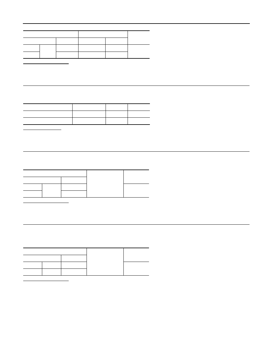
Check continuity between the IPDM E/R harness connector terminal and the ground.

Does continuity exist?

YES

>> Repair the harnesses or connectors. And then replace the fuse.

NO

>> Replace the fuse. (Replace IPDM E/R if the fuse is fusing again.)

5.

CHECK HEAD LAMP (HI) GROUND OPEN CIRCUIT

1.

Turn the ignition switch OFF.

2.

Disconnect the front combination lamp connector.

3.

Check continuity between the front combination lamp harness connector and the ground.

Does continuity exist?

YES

>> Replace the headlamp (HI) bulb. (Bulb socket is abnormally.)

NO

>> Repair the harnesses or connectors.

IPDM E/R

Front combination lamp

Continuity

Connector

Terminal

Connector

Terminal

RH

E8

89

E28

7

Existed

LH

90

E58

7

Unit

Location

Fuse No.

Capacity

Headlamp HI (RH) IPDM E/R

#55

10 

A

Headlamp HI (LH) 

IPDM E/R

#54

10 A

IPDM E/R 

Ground

Continuity

Connector

Terminal

RH

E8

89

Not existed

LH

90

Front combination lamp 

Ground

Continuity

Connector

Terminal

RH

E28

2

Existed

LH

E58

2

HEADLAMP (LO) CIRCUIT

EXL-69

< COMPONENT DIAGNOSIS >

[XENON TYPE]

C

D

E

F

G

H

I

J

K

M

A

B

EXL

N

O

P

HEADLAMP (LO) CIRCUIT

Description

INFOID:0000000003534174

Headlamp (LO) circuit is connected to HID control unit integrated in the headlamp. Headlamp (LO) circuit turns
xenon headlamp ON.
For the details of HID control unit and the xenon headlamp, refer to 

EXL-71, "Description"

.

Component Function Check

INFOID:0000000003534175

1.

CHECK HEADLAMP (LO) OPERATION

IPDM E/R AUTO ACTIVE TEST

1.

Activate IPDM E/R auto active test. Refer to 

PCS-11, "Diagnosis Description"

.

2.

Check that the headlamp is turned ON.

CONSULT-III ACTIVE TEST

1.

Select “EXTERNAL LAMP” of IPDM E/R active test item.

2.

With operating the test items, check that the headlamp (LO) is turned ON.

Is the headlamp (LO) turned ON?

YES

>> Headlamp (LO) is normal.

NO

>> Refer to 

EXL-69, "Diagnosis Procedure"

.

Diagnosis Procedure

INFOID:0000000003534176

1.

CHECK HEADLAMP (LO) OUTPUT VOLTAGE

CONSULT-III ACTIVE TEST

1.

Turn the ignition switch OFF.

2.

Disconnect the front combination lamp connector.

3.

Turn the ignition switch ON.

4.

Select “EXTERNAL LAMP” of IPDM E/R active test item.

5.

With operating the test items, check the voltage between the IPDM E/R harness connector and the
ground.

Is the measurement value normal?

YES

>> GO TO 2.

NO

>> GO TO 3.

2.

CHECK HEADLAMP (LO) OPEN CIRCUIT

1.

Turn the ignition switch OFF.

2.

Disconnect IPDM E/R connector.

3.

Check continuity between the IPDM E/R harness connector and the front combination lamp harness con-
nector.

Lo

: Headlamp (LO) ON

Off

: Headlamp (LO) OFF

Terminals

Test item

Voltage

(Approx.)

(+)

(

)

IPDM E/R

Ground

EXTERNAL 

LAMP

Connector

Terminal

RH

E8

83

Lo

Battery volt-

age

Off

0 V

LH

84

Lo

Battery volt-

age

Off

0 V

EXL-70

< COMPONENT DIAGNOSIS >

[XENON TYPE]

HEADLAMP (LO) CIRCUIT

Does continuity exist?

YES

>> GO TO 5.

NO

>> Repair the harnesses or connectors.

3.

CHECK HEADLAMP (LO) FUSE

1.

Turn the ignition switch OFF.

2.

Check that the following fuses are not fusing.

Is the fuse fusing?

YES

>> GO TO 4.

NO

>> Replace IPDM E/R.

4.

CHECK HEADLAMP (LO) SHORT CIRCUIT

1.

Disconnect IPDM E/R connector.

2.

Check continuity between the IPDM E/R harness connector and the ground.

Does continuity exist?

YES

>> Repair the harnesses or connectors. And then replace the fuse.

NO

>> Replace the fuse. (Replace IPDM E/R if the fuse is fusing again.)

5.

CHECK HEADLAMP (LO) GROUND OPEN CIRCUIT

1.

Turn the ignition switch OFF.

2.

Disconnect the front combination lamp connector.

3.

Check continuity between the front combination lamp harness connector and the ground.

Does continuity exist?

YES

>> Perform the xenon headlamp diagnosis. Refer to 

EXL-71, "Diagnosis Procedure"

.

NO

>> Repair the harnesses or connectors.

IPDM E/R

Front combination lamp

Continuity

Connector

Terminal

Connector

Terminal

RH

E8

83

E28

5

Existed

LH

84

E58

5

Unit

Lotion

Fuse No.

Capacity

Headlamp LO (RH) 

IPDM E/R

#57

15 A

Headlamp LO (LH) 

IPDM E/R

#56

15 A

IPDM E/R

Ground

Continuity

Connector

Terminal

RH

E8

83

Not existed

LH

84

Front combination lamp

Ground

Continuity

Connector

Terminal

RH

E28

3

Existed

LH

E58

3

XENON HEADLAMP

EXL-71

< COMPONENT DIAGNOSIS >

[XENON TYPE]

C

D

E

F

G

H

I

J

K

M

A

B

EXL

N

O

P

XENON HEADLAMP

Description

INFOID:0000000003135335

OUTLINE

• The lamp light source is by the arch discharge by applying high voltage into the xenon gas-filled bulb instead

of the halogen bulb filament. 

• Sight becomes more natural and brighter because the amount of light are gained adequately and the color of

light is sunshine-like white. 

• The xenon bulb drops the amount of light, repeats blinking, and illuminates in red if the bulb reaches the ser-

vice life.

ILLUMINATION PRINCIPLE

1.

 Discharging starts in high voltage pulse between bulb elec-
trodes.

2.

Xenon gas is activated by current between electrodes. Pale light
is emitted.

3.

The luminous tube (bulb) temperature elevates. Evaporated
halide is activated by discharge. The color of light changes into
white.

NOTE:
• Brightness and the color of light may change slightly immediately

after the headlamp turned ON until the xenon bulb becomes sta-
ble. This is not malfunction.

• Illumination time lag may occur between right and left. This is not

malfunction.

PRECAUTIONS FOR TROUBLE DIAGNOSIS

Representative malfunction examples are; "Light does not turn ON", "Light blinks", and "Brightness is inade-
quate." The cause often be the xenon bulb. Such malfunctions, however, are occurred occasionally by HID
control unit malfunction or lamp case malfunction. Specify the malfunctioning part with diagnosis procedure. 

WARNING:

• Never touch the harness, HID control unit, the inside and metal part of lamp when turning the head-

lamp ON or operating the light switch. 

• Never work with wet hands.

CAUTION:

• Never perform HID control unit circuit diagnosis with a circuit tester or an equivalent.
• Temporarily install the headlamp on the vehicle. Connect the battery to the connector (vehicle side)

when checking ON/OFF status.

• Disconnect the battery negative terminal before disconnecting the lamp socket connector or the har-

ness connector.

• Check for fusing of the fusible link(s), open around connector, short, disconnection if the symptom

is caused by electric error.

NOTE:
• Turn the switch OFF once before turning ON, if the ON/OFF is inoperative.
• The xenon bulb drops the amount of light, repeats blinking, and illuminates in red if the bulb reaches the ser-

vice life.

Diagnosis Procedure

INFOID:0000000003135336

1.

CHECK XENON BULB

Install the normal bulb to the applicable headlamp. Check that the xenon bulb is turned ON.

Is the headlamp turned ON?

YES

>> Replace the xenon bulb.

NO

>> GO TO 2.

2.

CHECK HID CONTROL UNIT

Install the normal HID control unit to the applicable headlamp. Check that the lamp is turned ON.

Is the headlamp turned ON?

JPLIA0421GB


Content   ..  754  755  756  757   ..