Infiniti EX35. Manual - part 716
TIMING CHAIN
EM-63
< ON-VEHICLE REPAIR >
C
D
E
F
G
H
I
J
K
L
M
A
EM
N
P
O
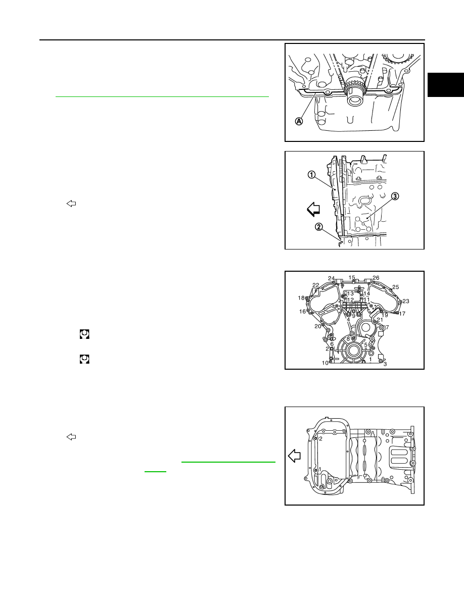
b.
Apply liquid gasket to top surface of oil pan (upper) as shown in
the figure.
Use Genuine RTV silicone Sealant or equivalent. Refer to
GI-15, "Recommended Chemical Products and Sealants"
.
c.
Assemble front timing chain case.
CAUTION:
• Be careful not to damage front oil seal by interference
with front end of crankshaft.
• Attaching should be done within 5 minutes after liquid
gasket application.
d.
Install front timing chain case as to fit its dowel pin hole together dowel pin on rear timing chain case.
e.
Tighten mounting bolts to the specified torque in numerical order
as shown in the figure.
• There are two types of mounting bolts. Refer to the following
for locating bolts.
f.
After all bolts are tightened, retighten them to the specified
torque in numerical order shown in the figure.
CAUTION:
Be sure to wipe off any excessive liquid gasket leaking on surface mating with oil pan (upper).
g.
Install two mounting bolts in front of oil pan (upper) in numerical
order shown in the figure.
11. Install valve timing control covers (bank 1 and bank 2) as follows:
A
:
φ
4.0 - 5.0 mm (0.157 - 0.197 in)
JPBIA0056ZZ
1
: Front timing chain case
2
: Oil pan (upper)
3
: Cylinder block
: Engine front
M10 bolts
: 1, 2, 3, 4, 5, 6, 7
: 55.0 N·m (5.6 kg-m, 41 ft-lb)
M6 bolts
: Except the above
: 12.7 N·m (1.3 kg-m, 9 ft-lb)
: Engine front
Tightening torque
: Refer to
JPBIA0058ZZ
JPBIA0046ZZ
JPBIA0047ZZ