Infiniti EX35. Manual - part 686
EC-486
< ECU DIAGNOSIS >
[VQ35HR]
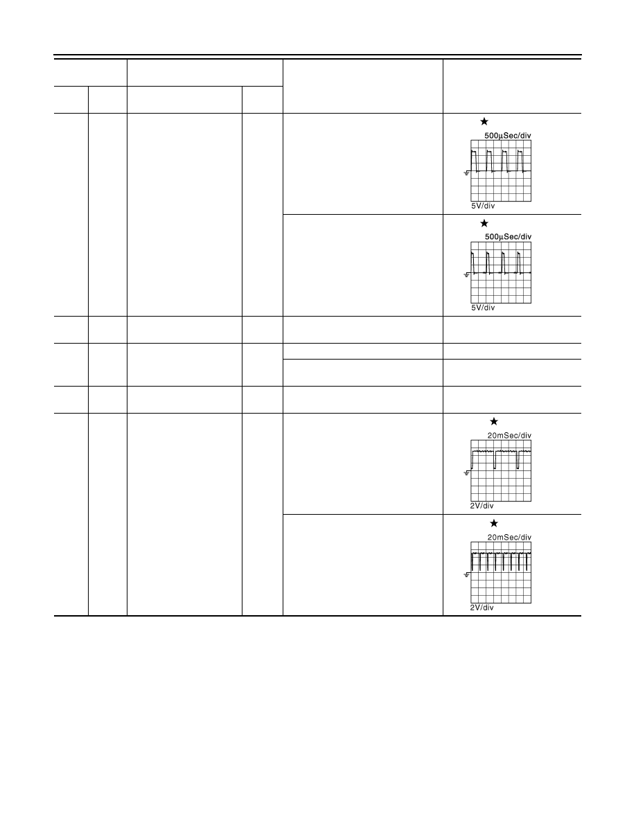
ECM
50
(V)
128
(B)
Throttle control motor
(Open) (bank 2)
Output
[Ignition switch: ON]
• Engine stopped
• Selector lever: D
• Accelerator pedal: Fully depressed
0 - 14 V
[Ignition switch: ON]
• Engine stopped
• Selector lever: D
• Accelerator pedal: Fully released
0 - 14 V
52
(R)
128
(B)
Throttle control motor relay
power supply (bank 2)
Input
[Ignition switch: ON]
BATTERY VOLTAGE
(11 - 14 V)
53
(P)
128
(B)
Ignition switch
Input
[Ignition switch: OFF]
0V
[Ignition switch: ON]
BATTERY VOLTAGE
(11 - 14 V)
57
(L)
128
(B)
A/F sensor 1 (bank 1)
Input
[Ignition switch: ON]
2.2 V
58
(GR)
88
(LG)
Exhaust valve timing con-
trol position sensor (bank
1)
Input
[Engine is running]
• Warm-up condition
• Idle speed
NOTE:
The pulse cycle changes depending
on rpm at idle
4.0 - 5.0 V
[Engine is running]
• Warm-up condition
• Engine speed: 2,000 rpm
4.0 - 5.0 V
Terminal No.
(Wire color)
Description
Condition
Value
(Approx.)
+
-–
Signal name
Input/
Output
JMBIA0031GB
JMBIA0032GB
JMBIA0043GB
JMBIA0044GB