Infiniti EX35. Manual - part 678


  Index      Infiniti     Infiniti EX35 - service repair manual 2008 year


Search            


Content   ..  676  677  678  679   ..


Infiniti EX35. Manual - part 678


EC-454

< COMPONENT DIAGNOSIS >

[VQ35HR]

FUEL PUMP

Check the following.
• Harness connectors E104, B4
• IPDM E/R harness connector E5
• Harness for open or short between IPDM E/R and “fuel level sensor unit and fuel pump (main)”

>> Repair open circuit or short to power in harness or connectors.

8.

CHECK FUEL PUMP GROUND CIRCUIT

1.

Turn ignition switch OFF.

2.

Disconnect dropping resistor harness connector.

3.

Check the continuity between “fuel level sensor unit and fuel pump (main)” harness connector and
ground.

4.

Also check harness for short to power.

Is the inspection result normal?

YES

>> GO TO 9.

NO

>> Repair open circuit or short to power in harness or connectors.

9.

CHECK FUEL PUMP

Refer to 

EC-454, "Component Inspection"

.

Is the inspection result normal?

YES

>> GO TO 10.

NO

>> Replace fuel pump.

10.

CHECK INTERMITTENT INCIDENT

Refer to 

GI-38, "Intermittent Incident"

.

Is the inspection result normal?

YES

>> Replace IPDM E/R.

NO

>> Repair or replace harness or connectors.

Component Inspection

INFOID:0000000003133640

1.

CHECK FUEL PUMP

1.

Turn ignition switch OFF.

2.

Disconnect “fuel level sensor unit and fuel pump (main)” harness connector.

3.

Check resistance between “fuel level sensor unit and fuel pump” terminals as follows.

Is the inspection result normal?

YES

>> INSPECTION END

NO

>> Replace “fuel level sensor unit and fuel pump”

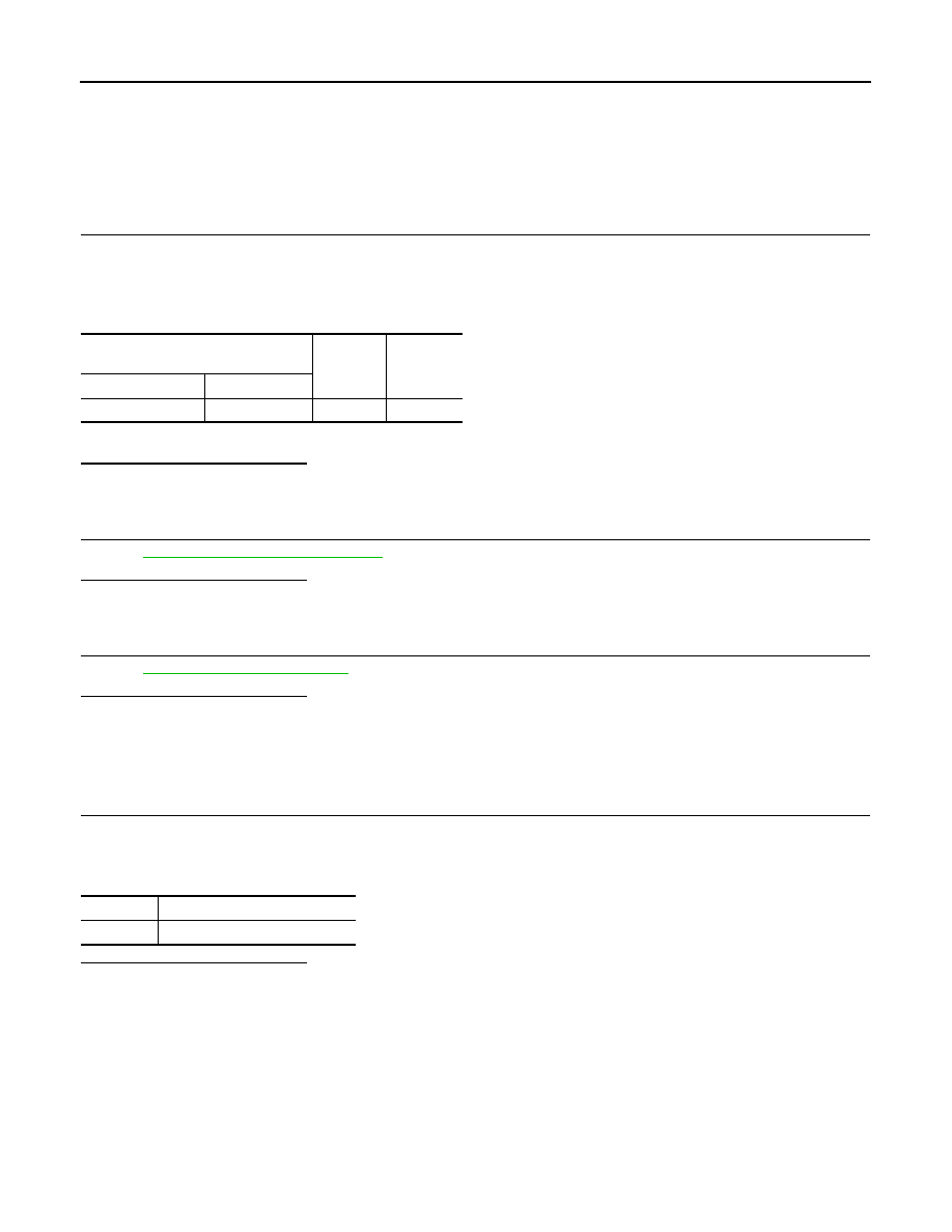
Fuel level sensor unit and fuel pump 

(main)

Ground

Continuity

Connector

Terminal

B22

3

Ground

Existed

Terminals

Resistance

1 and 3

0.2 - 5.0 

 [at 25

°

C (77

°

F)]

ICC BRAKE SWITCH

EC-455

< COMPONENT DIAGNOSIS >

[VQ35HR]

C

D

E

F

G

H

I

J

K

L

M

A

EC

N

P

O

ICC BRAKE SWITCH

Description

INFOID:0000000003133641

When the brake pedal is depressed, ICC brake switch is turned OFF and stop lamp switch is turned ON. ECM
detects the state of the brake pedal by this input of two kinds (ON/OFF signal).
Refer to 

CCS-17, "System Description"

 for the ICC function.

Component Function Check

INFOID:0000000003133642

1.

CHECK ICC BRAKE SWITCH FUNCTION

 With CONSULT-III

1.

Turn ignition switch ON.

2.

Select “BRAKE SW1” in “DATA MONITOR” mode with CONSULT-III.

3.

Check “BRAKE SW1” indication under the following conditions.

 Without CONSULT-III

1.

Turn ignition switch ON.

2.

Check the voltage between ECM harness connector terminals as follows.

Is the inspection result normal?

YES

>> INSPECTION END

NO

>> Go to 

EC-455, "Diagnosis Procedure"

.

Diagnosis Procedure

INFOID:0000000003133643

1.

CHECK ICC BRAKE SWITCH POWER SUPPLY CIRCUIT

1.

Turn ignition switch OFF.

2.

Disconnect ICC brake switch harness connector.

3.

Turn ignition switch ON.

4.

Check the voltage between ICC brake switch harness connector and ground.

Is the inspection result normal?

YES

>> GO TO 3.

NO

>> GO TO 2.

2.

DETECT MALFUNCTIONING PART

Check the following.
• Fuse block (J/B) connector E103
• 10A fuse (No. 3)
• Harness for open or short between ICC brake switch and fuse

Monitor item

Condition

Indication

BRAKE SW1

Brake pedal

Slightly depressed

OFF

Fully released

ON

ECM

Condition

Voltage (V)

Connector

+

Terminal

Terminal

M107

126

(ICC brake switch signal)

128

Brake pedal

Slightly depressed

Approx. 0

Fully released

Battery voltage

ICC brake switch

Ground

Voltage

Connector

Terminal

E114

1

Ground

Battery voltage

EC-456

< COMPONENT DIAGNOSIS >

[VQ35HR]

ICC BRAKE SWITCH

>> Repair open circuit or short to ground in harness or connectors.

3.

CHECK ICC BRAKE SWITCH INPUT SIGNAL CIRCUIT FOR OPEN AND SHORT-II

1.

Turn ignition switch OFF.

2.

Disconnect ECM harness connector.

3.

Check the continuity between ICC brake switch harness connector and ECM harness connector.

4.

Also check harness for short to ground and short to power.

Is the inspection result normal?

YES

>> GO TO 5.

NO

>> GO TO 4.

4.

DETECT MALFUNCTIONING PART

Check the following.
• Harness connectors E106, M6
• Harness for open or short between ICC brake switch and ECM

>> Repair open circuit or short to ground or short to power in harness or connectors.

5.

CHECK ICC BRAKE SWITCH

Refer to 

EC-456, "Component Inspection (ICC Brake Switch)"

.

Is the inspection result normal?

YES

>> GO TO 6.

NO

>> Replace ICC brake switch.

6.

CHECK INTERMITTENT INCIDENT

Refer to 

GI-38, "Intermittent Incident"

.

>> INSPECTION END

Component Inspection (ICC Brake Switch)

INFOID:0000000003133644

1.

CHECK ICC BRAKE SWITCH-I

1.

Turn ignition switch OFF.

2.

Disconnect ICC brake switch harness connector.

3.

Check the continuity between ICC brake switch terminals under the following conditions.

Is the inspection result normal?

YES

>> INSPECTION END

NO

>> GO TO 2.

2.

CHECK ICC BRAKE SWITCH-II

1.

Adjust ICC brake switch installation. Refer to 

BR-7, "Inspection and Adjustment"

.

2.

Check the continuity between ICC brake switch terminals under the following conditions.

ICC brake switch

ECM

Continuity

Connector

Terminal

Connector

Terminal

E114

2

M107

126

Existed

Terminals

Condition

Continuity

1 and 2

Brake pedal

Fully released

Existed

Slightly depressed

Not existed

Terminals

Condition

Continuity

1 and 2

Brake pedal

Fully released

Existed

Slightly depressed

Not existed

ICC BRAKE SWITCH

EC-457

< COMPONENT DIAGNOSIS >

[VQ35HR]

C

D

E

F

G

H

I

J

K

L

M

A

EC

N

P

O

Is the inspection result normal?

YES

>> INSPECTION END

NO

>> Replace ICC brake switch.


Content   ..  676  677  678  679   ..