Infiniti EX35. Manual - part 653


  Index      Infiniti     Infiniti EX35 - service repair manual 2008 year


Search            


Content   ..  651  652  653  654   ..


Infiniti EX35. Manual - part 653


EC-354

< COMPONENT DIAGNOSIS >

[VQ35HR]

P1217 ENGINE OVER TEMPERATURE

>> Repair or replace malfunctioning part.

4.

CHECK RADIATOR CAP

Check radiator cap. Refer to 

CO-11, "RADIATOR CAP : Inspection"

.

Is the inspection result normal?

YES

>> GO TO 5.

NO

>> Replace radiator cap.

5.

CHECK THERMOSTAT

Check thermostat. Refer to 

CO-22, "Inspection"

.

Is the inspection result normal?

YES

>> GO TO 6.

NO

>> Replace thermostat

6.

CHECK ENGINE COOLANT TEMPERATURE SENSOR

Refer to 

EC-174, "Component Inspection"

.

Is the inspection result normal?

YES

>> GO TO 7.

NO

>> Replace engine coolant temperature sensor.
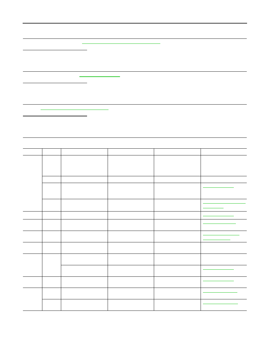
7.

CHECK MAIN 12 CAUSES

If the cause cannot be isolated, check the following.

*1: Turn the ignition switch ON.

*2: Engine running at 3,000 rpm for 10 minutes.

*3: Drive at 90 km/h (56 MPH) for 30 minutes and then let idle for 10 minutes.

*4: After 60 minutes of cool down time.

Engine

Step

Inspection item

Equipment

Standard

Reference page

OFF

1

• Blocked radiator
• Blocked condenser
• Blocked radiator grille
• Blocked bumper

• Visual

No blocking

2

• Coolant mixture

• Coolant tester

50 - 50% coolant mixture

3

• Coolant  level

• Visual

Coolant up to MAX level in 
reservoir tank and radiator 
filler neck

CO-7, "Inspection"

4

• Radiator cap

• Pressure tester

107 kPa

(1.1 kg/cm

2

, 16 psi) (Limit)

CO-11, "RADIATOR CAP 
: Inspection"

ON*

2

5

• Coolant leaks

• Visual

No leaks

CO-7, "Inspection"

ON*

2

6

• Thermostat

• Touch the upper and 

lower radiator hoses

Both hoses should be hot

CO-22, "Inspection"

ON*

1

7

• Cooling fan

• CONSULT-III

Operating

EC-443, "Component 
Function Check"

OFF

8

• Combustion gas leak

• Color checker chemical 

tester 4 Gas analyzer

Negative

ON*

3

9

• Coolant temperature 

gauge

• Visual

Gauge less than 3/4 when 
driving

• Coolant overflow to res-

ervoir tank

• Visual

No overflow during driving 
and idling

CO-7, "Inspection"

OFF*

4

10

• Coolant return from res-

ervoir tank to radiator

• Visual

Should be initial level in 
reservoir tank

CO-7, "Inspection"

OFF

11

• Cylinder head

• Straight gauge feeler 

gauge

0.1 mm (0.004 in) Maxi-
mum distortion (warping)

EM-111, "Inspection"

12

• Cylinder block and pis-

tons

• Visual

No scuffing on cylinder 
walls or piston

EM-123, "Inspection"

P1217 ENGINE OVER TEMPERATURE

EC-355

< COMPONENT DIAGNOSIS >

[VQ35HR]

C

D

E

F

G

H

I

J

K

L

M

A

EC

N

P

O

For more information, refer to 

CO-3, "Troubleshooting Chart"

.

>> INSPECTION END

EC-356

< COMPONENT DIAGNOSIS >

[VQ35HR]

P1225, P1234 TP SENSOR

P1225, P1234 TP SENSOR

Description

INFOID:0000000003133513

Electric throttle control actuator consists of throttle control motor,
throttle position sensor, etc. The throttle position sensor responds to
the throttle valve movement. 
The throttle position sensor has two sensors. These sensors are a
kind of potentiometers which transform the throttle valve position into
output voltage, and emit the voltage signal to the ECM. In addition,
these sensors detect the opening and closing speed of the throttle
valve and feed the voltage signals to the ECM. The ECM judges the
current opening angle of the throttle valve from these signals and the
ECM controls the throttle control motor to make the throttle valve
opening angle properly in response to driving condition.

DTC Logic

INFOID:0000000003133514

DTC DETECTION LOGIC

DTC CONFIRMATION PROCEDURE

1.

PRECONDITIONING

If DTC Confirmation Procedure has been previously conducted, always turn ignition switch OFF and wait at
least 10 seconds before conducting the next test.
TESTING CONDITION:
Before performing the following procedure, confirm that battery voltage is more than 10 V at idle.

>> GO TO 2.

2.

PERFORM DTC CONFIRMATION PROCEDURE

1.

Turn ignition switch ON.

2.

Turn ignition switch OFF and wait at least 10 seconds.

3.

Turn ignition switch ON.

4.

Check 1st trip DTC.

Is 1st trip DTC detected?

YES

>> Go to 

EC-356, "Diagnosis Procedure"

.

NO

>> INSPECTION END

Diagnosis Procedure

INFOID:0000000003133515

1.

CHECK ELECTRIC THROTTLE CONTROL ACTUATOR VISUALLY

1.

Turn ignition switch OFF.

2.

Remove the intake air duct.

PBIB0145E

DTC No.

Trouble diagnosis name

DTC detecting condition

Possible cause

P1225

Closed throttle position learning per-
formance (bank 1)

Closed throttle position learning value 
is excessively low.

• Electric throttle control actuator

(TP sensor 1 and 2)

P1234

Closed throttle position learning per-
formance (bank 2)

P1225, P1234 TP SENSOR

EC-357

< COMPONENT DIAGNOSIS >

[VQ35HR]

C

D

E

F

G

H

I

J

K

L

M

A

EC

N

P

O

3.

Check if foreign matter is caught between the throttle valve (1)
and the housing.

Is the inspection result normal?

YES

>> GO TO 2.

NO

>> Remove the foreign matter and clean the electric throttle

control actuator inside.

2.

REPLACE ELECTRIC THROTTLE CONTROL ACTUATOR

1.

Replace malfunctioning electric throttle control actuator.

2.

Go to 

EC-357, "Special Repair Requirement"

.

>> INSPECTION END

Special Repair Requirement

INFOID:0000000003133516

1.

PERFORM THROTTLE VALVE CLOSED POSITION LEARNING

Refer to 

EC-17, "THROTTLE VALVE CLOSED POSITION LEARNING : Special Repair Requirement"

>> GO TO 2.

2.

PERFORM IDLE AIR VOLUME LEARNING

Refer to 

EC-18, "IDLE AIR VOLUME LEARNING : Special Repair Requirement"

>> END

JMBIA0025ZZ


Content   ..  651  652  653  654   ..