Infiniti EX35. Manual - part 650


  Index      Infiniti     Infiniti EX35 - service repair manual 2008 year


Search            


Content   ..  648  649  650  651   ..


Infiniti EX35. Manual - part 650


EC-342

< COMPONENT DIAGNOSIS >

[VQ35HR]

P0850 PNP SWITCH

4.

Check 1st trip DTC.

Is 1st trip DTC detected?

YES

>> Go to 

EC-342, "Diagnosis Procedure"

.

NO

>> INSPECTION END

5.

PERFORM COMPONENT FUNCTION CHECK

Perform component function check. Refer to 

EC-342, "Component Function Check"

.

NOTE:
Use component function check to check the overall function of the park/neutral position (PNP) signal circuit.
During this check, a 1st trip DTC might not be confirmed.

Is the inspection result normal?

YES

>> INSPECTION END

NO

>> Go to 

EC-342, "Diagnosis Procedure"

.

Component Function Check

INFOID:0000000003133497

1.

PERFORM COMPONENT FUNCTION CHECK

1.

Turn ignition switch ON.

2.

Check the voltage between ECM harness connector terminals under the following conditions.

Is the inspection result normal?

YES

>> INSPECTION END

NO

>> Go to 

EC-342, "Diagnosis Procedure"

.

Diagnosis Procedure

INFOID:0000000003133498

1.

CHECK DTC WITH TCM

Refer to 

TM-39, "Diagnosis Description"

.

Is the inspection result normal?

YES

>> GO TO 2.

NO

>> Repair or replace malfunctioning part.

2.

CHECK STARTING SYSTEM

Turn ignition switch OFF, then turn it to START.
Does starter motor operate?

YES

>> GO TO 3.

NO

>> Check DTC with BCM. Refer to 

BCS-16, "COMMON ITEM : CONSULT-III Function (BCM - COM-

MON ITEM)"

.

3.

CHECK PNP SIGNAL CIRCUIT FOR OPEN AND SHORT

1.

Turn ignition switch OFF.

2.

Disconnect A/T assembly harness connector.

3.

Disconnect ECM harness connector.

4.

Check the continuity between A/T assembly harness connector and ECM harness connector.

5.

Also check harness for short to ground and short to power.
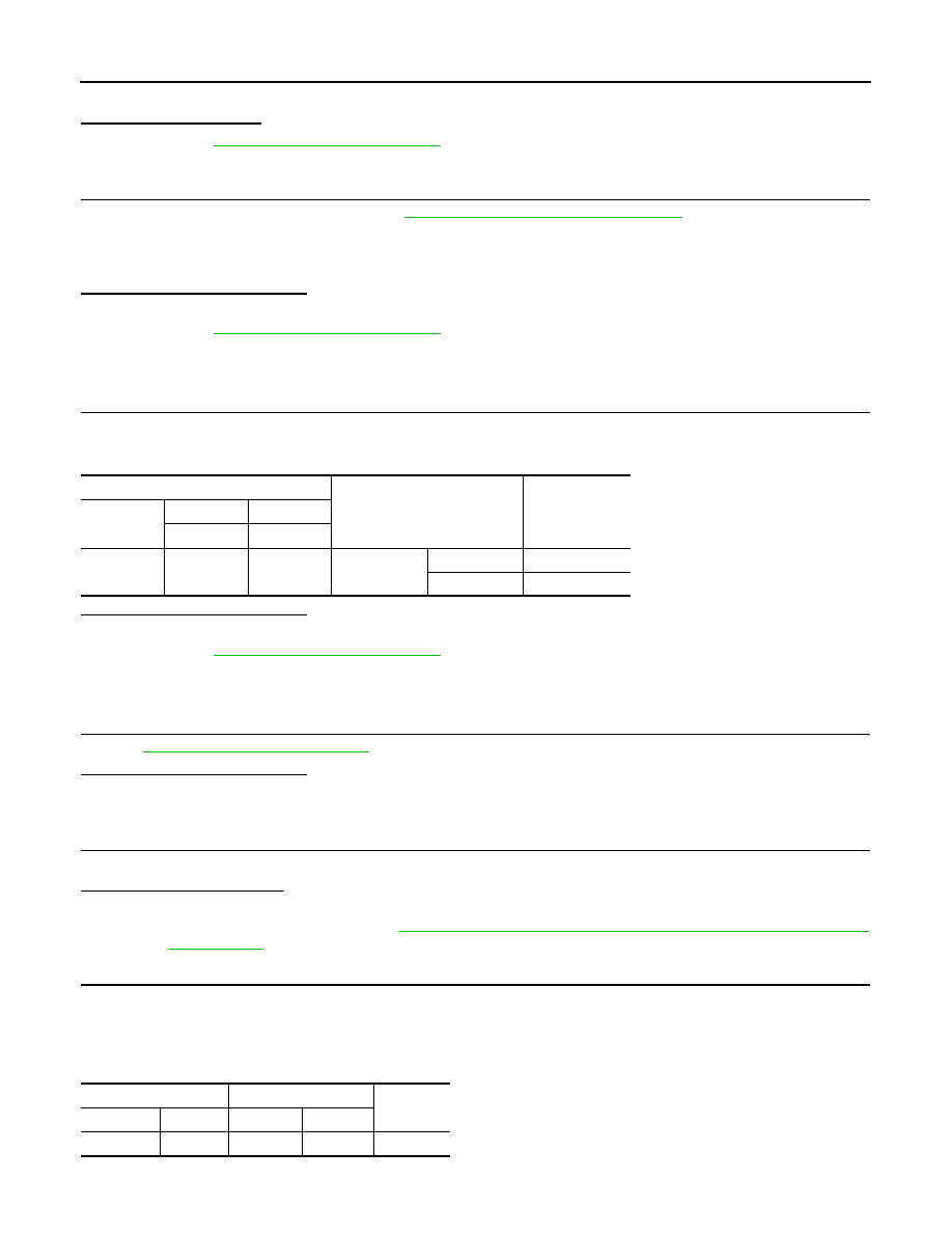
ECM

Condition

Voltage (V)

Connector

+

Terminal

Terminal

M107

109

128

Selector lever

P or N

Battery voltage

Except above

Approx. 0

A/T assembly

ECM

Continuity

Connector

Terminal

Connector

Terminal

F51

9

M107

109

Existed

P0850 PNP SWITCH

EC-343

< COMPONENT DIAGNOSIS >

[VQ35HR]

C

D

E

F

G

H

I

J

K

L

M

A

EC

N

P

O

Is the inspection result normal?

YES

>> GO TO 5.

NO

>> GO TO 4.

4.

DETECT MALFUNCTIONING PART

Check the following.
• Harness connectors F1, E3
• Harness connectors E106, M6
• Harness for open or short between A/T assembly and ECM

>> Repair open circuit or short to ground or short to power in harness or connectors.

5.

CHECK INTERMITTENT INCIDENT

Refer to 

GI-38, "Intermittent Incident"

.

>> INSPECTION END

EC-344

< COMPONENT DIAGNOSIS >

[VQ35HR]

P1078, P1084 EVT CONTROL POSITION SENSOR

P1078, P1084 EVT CONTROL POSITION SENSOR

Description

INFOID:0000000003133499

Exhaust valve timing control position sensor detects the concave
groove of the exhaust camshaft rear end. 
This sensor signal is used for sensing a position of the exhaust cam-
shaft.
This sensor uses a Hall IC.
Based on the position of the exhaust camshaft, ECM controls
exhaust valve timing control magnet retarder to optimize the shut/
open timing of exhaust valve for the driving condition.

DTC Logic

INFOID:0000000003133500

DTC DETECTION LOGIC

NOTE:
If DTC P1078 is displayed with DTC P0643, first perform the trouble diagnosis for DTC P0643. Refer to

EC-339, "DTC Logic"

.

DTC CONFIRMATION PROCEDURE

1.

PRECONDITIONING

If DTC Confirmation Procedure has been previously conducted, always turn ignition switch OFF and wait at
least 10 seconds before conducting the next test.

JMBIA0064ZZ

DTC No.

Trouble diagnosis name

DTC detecting condition

Possible cause

P1078

Exhaust valve timing 
control position sensor 
(bank 1) circuit

An excessively high or low voltage from 
the sensor is sent to ECM.

• Harness or connectors

[EVT control position sensor (bank 1) circuit is 
open or shorted)

• Exhaust valve timing control position sensor
• Crankshaft position sensor (POS)
• Camshaft position sensor (PHASE) (bank 1)
• Accumulation of debris to the signal pick-up 

portion of the camshaft

P1084

Exhaust valve timing 
control position sensor 
(bank 2) circuit

• Harness or connectors

[EVT control position sensor (bank 2) circuit is 
open or shorted)
[CKP sensor (POS) circuit is shorted.]
[CMP sensor (PHASE) (bank 2) circuit is short-
ed.]
(Battery current sensor circuit is shorted.)
(APP sensor 2 circuit is shorted.)
(EVAP control system pressure sensor circuit 
is shorted.)
(Refrigerant pressure sensor circuit is short-
ed.)

• Exhaust valve timing control position sensor 

(bank 2)

• Crankshaft position sensor (POS)
• Camshaft position sensor (PHASE) (bank 2)
• Battery current sensor
• Accelerator pedal position sensor
• EVAP control system pressure sensor
• Refrigerant pressure sensor
• Accumulation of debris to the signal pick-up 

portion of the camshaft

P1078, P1084 EVT CONTROL POSITION SENSOR

EC-345

< COMPONENT DIAGNOSIS >

[VQ35HR]

C

D

E

F

G

H

I

J

K

L

M

A

EC

N

P

O

>> GO TO 2.

2.

PERFORM DTC CONFIRMATION PROCEDURE

1.

Start engine and let it idle for 10 seconds.

2.

Check 1st trip DTC.

Is 1st trip DTC detected?

YES

>> Go to 

EC-345, "Diagnosis Procedure"

.

NO

>> INSPECTION END

Diagnosis Procedure

INFOID:0000000003133501

1.

CHECK GROUND CONNECTION

1.

Turn ignition switch OFF.

2.

Check ground connection M95. Refer to Ground Inspection in 

GI-41, "Circuit Inspection"

.

Is the inspection result normal?

YES

>> GO TO 2.

NO

>> Repair or replace ground connection.

2.

CHECK EXHAUST VALVE TIMING CONTROL POSITION SENSOR POWER SUPPLY CIRCUIT-I

1.

Disconnect exhaust valve timing control position sensor harness connector.

2.

Turn ignition switch ON.

3.

Check the voltage between exhaust valve timing control position sensor harness connector and ground.

Is the inspection result normal?

YES

>> GO TO 8.

NO-1

>> P1078: Repair open circuit or short to ground or short to power in harness or connectors.

NO-2

>> P1084: GO TO 3.

3.

CHECK EXHAUST VALVE TIMING CONTROL POSITION SENSOR POWER SUPPLY CIRCUIT-II

1.

Turn ignition switch OFF.

2.

Disconnect ECM harness connector.

3.

Check the continuity between exhaust valve timing control position sensor harness connector and ECM
harness connector.

Is the inspection result normal?

YES

>> GO TO 4.

NO

>> Repair open circuit.

4.

CHECK SENSOR POWER SUPPLY CIRCUIT

Check harness for short to power and short to ground, between the following terminals.

DTC

EVT control position sensor

Ground

Voltage (V)

Bank

Connector

Terminal

P1078

1

F4

1

Ground

Approx. 5

P1084

2

F19

1

EVT control position sensor

ECM

Continuity

Bank

Connector

Terminal

Connector

Terminal

2

F19

1

F102

64

Existed

ECM

Sensor

Connector

Terminal

Name

Connector

Terminal

F101

46

CKP sensor (POS)

F2

1


Content   ..  648  649  650  651   ..