Infiniti EX35. Manual - part 622
EC-230
< COMPONENT DIAGNOSIS >
[VQ35HR]
P0181 FTT SENSOR
YES
>> GO TO 7.
NO
>> GO TO 6.
6.
DETECT MALFUNCTIONING PART
Check the following.
• Harness connectors M7, B1
• Harness for open or short between “fuel level sensor unit and fuel pump (main)” and “unified meter and A/C
amp.”
>> Repair open circuit or short to ground or short to power in harness or connector.
7.
CHECK FUEL TANK TEMPERATURE SENSOR
EC-230, "Component Inspection"
Is the inspection result normal?
YES
>> GO TO 8.
NO
>> Replace “fuel level sensor unit and fuel pump (main)”.
8.
CHECK INTERMITTENT INCIDENT
GI-38, "Intermittent Incident"
>> INSPECTION END
Component Inspection
INFOID:0000000003133387
1.
CHECK FUEL TANK TEMPERATURE SENSOR
1.
Turn ignition switch OFF.
2.
Disconnect “fuel level sensor unit and fuel pump” harness connector.
3.
Remove fuel level sensor unit.
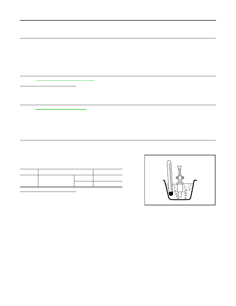
4.
Check resistance between “fuel level sensor unit and fuel pump”
terminals by heating with hot water as shown in the figure.
Is the inspection result normal?
YES
>> INSPECTION END
NO
>> Replace “fuel level sensor unit and fuel pump”.
Terminals
Condition
Resistance (k
Ω
)
4 and 5
Temperature
[
°
C
(
°
F)]
20 (68)
2.3 - 2.7
50 (122)
0.79 - 0.90
JMBIA0167ZZ