Infiniti EX35. Manual - part 608
EC-174
< COMPONENT DIAGNOSIS >
[VQ35HR]
P0117, P0118 ECT SENSOR
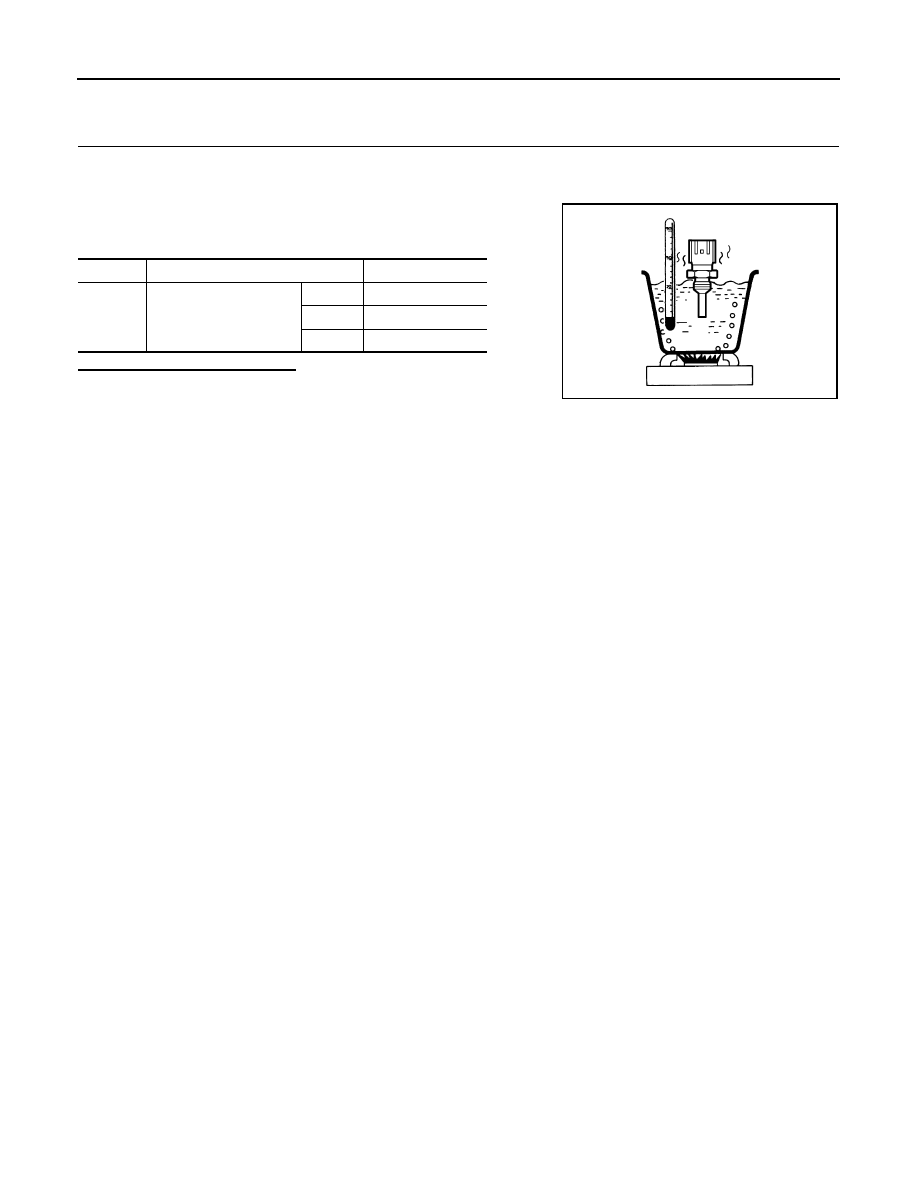
Component Inspection
INFOID:0000000003133335
1.
CHECK ENGINE COOLANT TEMPERATURE SENSOR
1.
Turn ignition switch OFF.
2.
Disconnect engine coolant temperature sensor harness connector.
3.
Remove engine coolant temperature sensor.
4.
Check resistance between engine coolant temperature sensor
terminals by heating with hot water as shown in the figure.
Is the inspection result normal?
YES
>> INSPECTION END
NO
>> Replace engine coolant temperature sensor.
Terminals
Condition
Resistance (k
Ω
)
1 and 2
Temperature [
°
C (
°
F)]
20 (68)
2.37 - 2.63
50 (122)
0.68 - 1.00
90 (194)
0.236 - 0.260
JMBIA0080ZZ