Infiniti EX35. Manual - part 522


  Index      Infiniti     Infiniti EX35 - service repair manual 2008 year


Search            


Content   ..  520  521  522  523   ..


Infiniti EX35. Manual - part 522


DLN-38

< SYMPTOM DIAGNOSIS >

[TRANSFER: ETX13B]

NOISE, VIBRATION AND HARSHNESS (NVH) TROUBLESHOOTING

NOISE, VIBRATION AND HARSHNESS (NVH) TROUBLESHOOTING

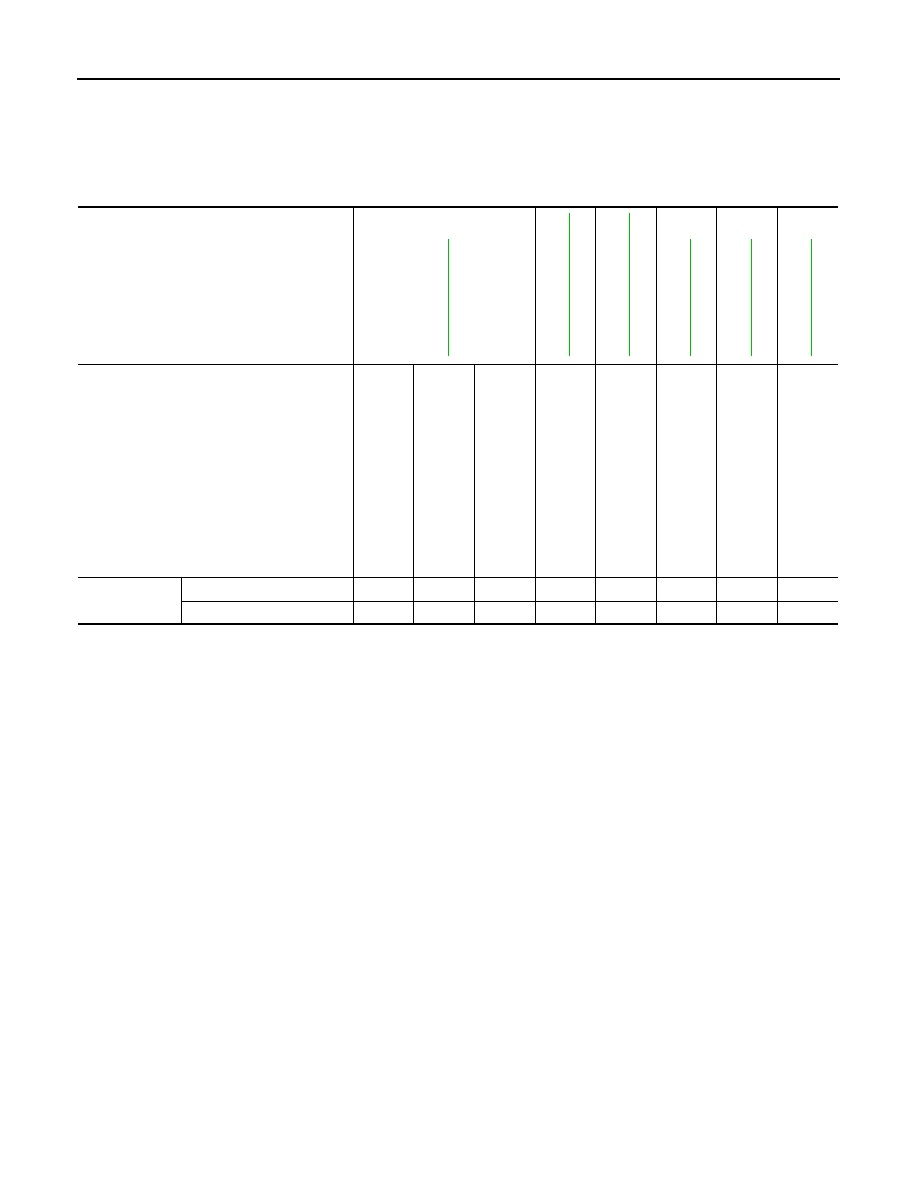
NVH Troubleshooting Chart

INFOID:0000000003702906

Use the chart below to help you find the cause of the symptom. The numbers indicate the order of the inspec-
tion. If necessary, repair or replace these parts.

Reference

DLN-43, "Inspection"

DLN-53, "Exploded 

V

iew"

DLN-53, "Exploded 

V

iew"

DLN-65, "Inspection"

DLN-65, "Inspection"

DLN-62, "Inspection"

SUSPECTED PARTS
(Possible cause)

TRANSF

ER FLUID (Level 

low)

TRANSF

ER FLUID (W

rong)

TRANSF

ER FLUID (Level 

too high)

LIQUID GASKET

 (Damaged)

OIL SEAL (W

orn or 

damaged)

GEAR (W

o

rn o

r da

m

a

g

ed)

BEAR

ING

 (W

orn

 o

da

ma

ge

d)

TRANSF

ER CASE 

(Damaged)

Symptom

Noise

1

2

3

3

3

Transfer fluid leakage

4

1

2

2

3

PRECAUTIONS

DLN-39

< PRECAUTION >

[TRANSFER: ETX13B]

C

E

F

G

H

I

J

K

L

M

A

B

DLN

N

O

P

PRECAUTION

PRECAUTIONS

Precaution for Supplemental Restraint System (SRS) "AIR BAG" and "SEAT BELT 
PRE-TENSIONER"

INFOID:0000000003739333

The Supplemental Restraint System such as “AIR BAG” and “SEAT BELT PRE-TENSIONER”, used along
with a front seat belt, helps to reduce the risk or severity of injury to the driver and front passenger for certain
types of collision. This system includes seat belt switch inputs and dual stage front air bag modules. The SRS
system uses the seat belt switches to determine the front air bag deployment, and may only deploy one front
air bag, depending on the severity of a collision and whether the front occupants are belted or unbelted.
Information necessary to service the system safely is included in the “SRS AIRBAG” and “SEAT BELT” of this
Service Manual.

WARNING:

• To avoid rendering the SRS inoperative, which could increase the risk of personal injury or death in

the event of a collision which would result in air bag inflation, all maintenance must be performed by
an authorized NISSAN/INFINITI dealer.

• Improper maintenance, including incorrect removal and installation of the SRS, can lead to personal

injury caused by unintentional activation of the system. For removal of Spiral Cable and Air Bag
Module, see the “SRS AIRBAG”.

• Do not use electrical test equipment on any circuit related to the SRS unless instructed to in this

Service Manual. SRS wiring harnesses can be identified by yellow and/or orange harnesses or har-
ness connectors.

Service Notice or Precautions for Transfer

INFOID:0000000003135713

CAUTION:

• Never reuse transfer fluid, once it has been drained.
• Check the fluid level or replace the fluid only with the vehicle parked on level ground.
• During removal or installation, keep inside of transfer clear of dust or dirt.
• Replace all tires at the same time. Always use tires of the proper size and the same brand and pat-

tern. Fitting improper size and unusually worn tires applies excessive force to vehicle mechanism
and can cause longitudinal vibration.

• Disassembly should be done in a clean work area, it is preferable to work in dustproof area.
• Before proceeding with disassembly, thoroughly clean the transfer. It is important to prevent the

internal parts from becoming contaminated by dirt or other foreign matter.

• All parts should be carefully cleaned with a general purpose, non-flammable solvent before inspec-

tion or reassembly.

• Check for the correct installation status prior to removal or disassembly. If matching marks are

required, be certain they do not interfere with the function of the parts when applied.

• Check appearance of the disassembled parts for damage, deformation, and unusual wear. Replace

them with a new ones if necessary.

• Gaskets, seals and O-rings should be replaced any time the transfer is disassembled.
• In principle, tighten bolts or nuts gradually in several steps working diagonally from inside to out-

side. If tightening sequence is specified, use it.

• Observe the specified torque when assembling.
• Clean and flush the parts sufficiently and blow-dry them.
• Be careful not to damage sliding surfaces and mating surfaces.
• Clean inner parts with lint-free cloth or towels. Do not use cotton work gloves and rags to prevent

adhering fibers.

DLN-40

< PREPARATION >

[TRANSFER: ETX13B]

PREPARATION

PREPARATION

PREPARATION

Special Service Tools

INFOID:0000000003135714

The actual shapes of Kent-Moore tools may differ from those of special service tools illustrated here.

Tool number
(Kent-Moore No.)
Tool name

Description

ST27862000
(

)

Drift
a: 62.5 mm (2.461 in) dia.
b: 42 mm (1.65 in) dia.

Installing front oil seal

KV381054S0
(J-34286)
Puller

Removing rear oil seal

ST30720000
(J-25405)
Drift
a: 77 mm (3.03 in) dia.
b: 55.5 mm (2.185 in) dia.

• Installing rear oil seal
• Installing mainshaft oil seal

KV40104830
(

)

Drift
a: 70 mm (2.76 in) dia.
b: 63.5 mm (2.500 in) dia.

Installing rear oil seal

KV38100300
(J-25523)
Drift
a: 54 mm (2.13 in) dia.
b: 46 mm (1.81 in) dia.
c: 32 mm (1.26 in) dia.

Removing mainshaft bearing

ST33052000
(

)

Drift
a: 28 mm (1.10 in) dia.
b: 22 mm (0.87 in) dia.

Removing mainshaft assembly

ZZA0194D

ZZA0601D

ZZA0811D

ZZA1003D

ZZA1046D

ZZA1000D

PREPARATION

DLN-41

< PREPARATION >

[TRANSFER: ETX13B]

C

E

F

G

H

I

J

K

L

M

A

B

DLN

N

O

P

Commercial Service Tools

INFOID:0000000003135715

ST30611000
(J-25742-1)
Drift bar
a: 350 mm (13.78 in)
b: 25 mm (0.98 in) dia.
c: M12 

×

 1.5P

Removing rear bearing

ST35321000
(

)

Drift
a: 49 mm (1.93 in) dia.
b: 41 mm (1.61 in) dia.

• Removing rear bearing
• Installing mainshaft assembly

KV38104010
(

)

Drift
a: 67 mm (2.64 in) dia.
b: 49 mm (1.93 in) dia.

• Installing front drive shaft rear bearing
• Installing rear bearing

ST30621000
(J-25742-5)
Drift
a: 80 mm (3.15 in) dia.
b: 59 mm (2.32 in) dia.

Installing mainshaft bearing

ST31214000
(J-25269-B)
Drift
a: 34 mm (1.34 in) dia.
b: 25.5 mm (1.004 in) dia.

• Removing front drive shaft front bearing
• Removing front drive shaft rear bearing

ST33200000
(J-26082)
Drift
a: 60 mm (2.36 in) dia.
b: 44.5 mm (1.752 in) dia.

Installing front drive shaft front bearing

Tool number
(Kent-Moore No.)
Tool name

Description

NT663

ZZA1000D

ZZA1000D

ZZA1000D

ZZA0534D

ZZA1002D


Content   ..  520  521  522  523   ..