Infiniti EX35. Manual - part 355
BRM-22
< REMOVAL AND INSTALLATION >
BODY ALIGNMENT
BODY ALIGNMENT
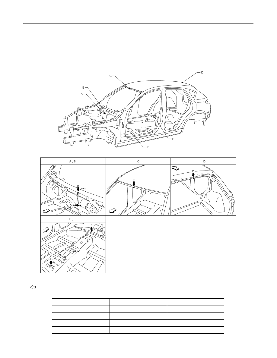
Body Center Marks
INFOID:0000000003134496
A mark has been placed on each part of the body to indicate the vehicle center. When repairing parts dam-
aged by an accident which might affect the vehicle frame (members, pillars, etc.), more accurate and effective
repair will be possible by using these marks together with body alignment specifications.
Unit: mm (in)
: Vehicle front
Points
Portion
Marks
A
Upper dash
Embossment
B
Upper dash crossmember
Bead
C
Front roof
Embossment
D
Rear roof
Indent
JSKIA0578ZZ