Infiniti EX35. Manual - part 329
DIAGNOSIS SYSTEM [ABS ACTUATOR AND ELECTRIC UNIT (CONTROL
UNIT)]
BRC-31
< FUNCTION DIAGNOSIS >
[VDC/TCS/ABS]
C
D
E
G
H
I
J
K
L
M
A
B
BRC
N
O
P
×
: Applicable
: Optional item
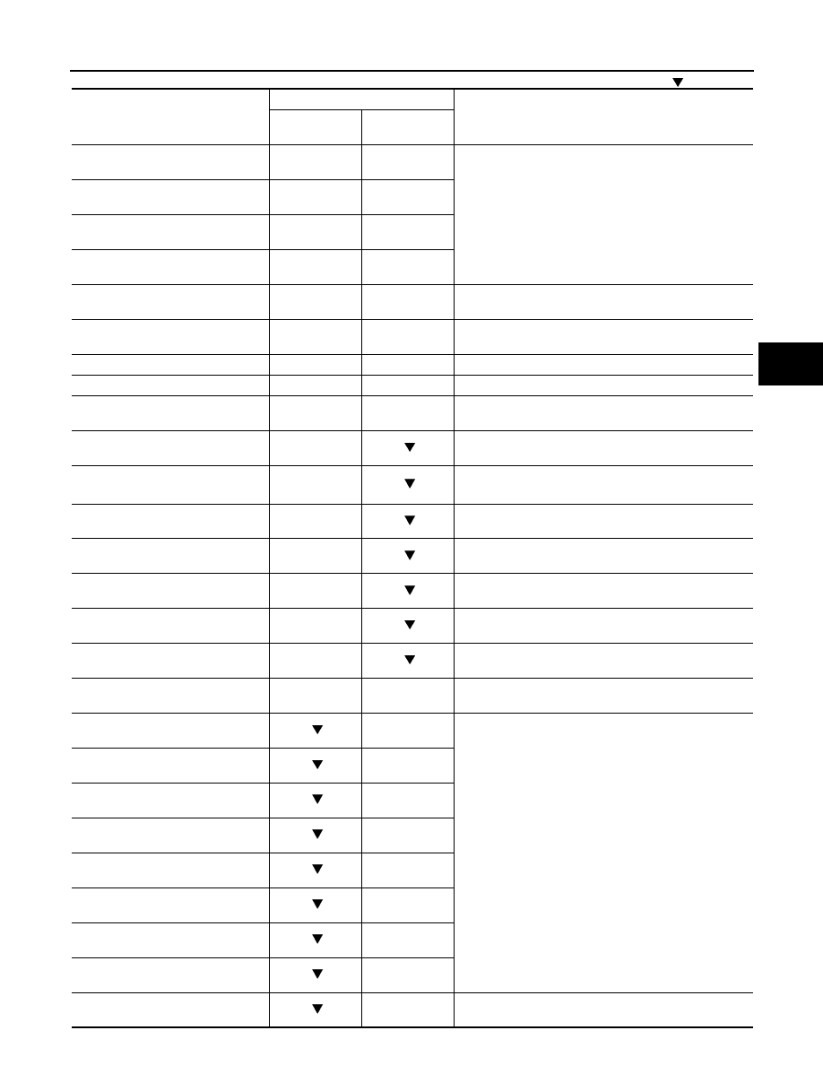
Monitor item (Unit)
SELECT MONITOR ITEM
Remarks
ECU INPUT
SIGNALS
MAIN SIGNALS
FR LH SENSOR
[km/h (MPH)]
×
×
Wheel speed
FR RH SENSOR
[km/h (MPH)]
×
×
RR LH SENSOR
[km/h (MPH)]
×
×
RR RH SENSOR
[km/h (MPH)]
×
×
STOP LAMP SW
(On/Off)
×
×
Stop lamp switch signal status
BATTERY VOLT
(V)
×
×
Battery voltage supplied to the ABS actuator and electric
unit (control unit)
GEAR
×
×
Gear position determined by TCM
SLCT LVR POSI
×
×
A/T selector lever position
YAW RATE SEN
(d/s)
×
×
Yaw rate detected by yaw rate/side G sensor
ACCEL POS SIG
(%)
×
Throttle actuator opening/closing is displayed (Linked with
accelerator pedal)
SIDE G-SENSOR
(m/s
2
)
×
Transverse G detected by yaw rate/side G sensor
STR ANGLE SIG
(
°
)
×
Steering angle detected by steering angle sensor
PRESS SENSOR
(bar)
×
Brake fluid pressure detected by pressure sensor
ENGINE RPM
[tr/min (rpm)]
×
Engine speed
FLUID LEV SW
(On/Off)
×
Brake fluid level switch signal status
PARK BRAKE SW
(On/Off)
×
Parking brake switch signal status
LDP) APP SEN
(%) (Note 2)
×
×
Accelerator pedal position sensor status received from
ECM via CAN communication
FR RH IN SOL
(On/Off) (Note 1)
×
Operation status of each solenoid valve
FR RH OUT SOL
(On/Off) (Note 1)
×
FR LH IN SOL
(On/Off) (Note 1)
×
FR LH OUT SOL
(On/Off) (Note 1)
×
RR RH IN SOL
(On/Off) (Note 1)
×
RR RH OUT SOL
(On/Off) (Note 1)
×
RR LH IN SOL
(On/Off) (Note 1)
×
RR LH OUT SOL
(On/Off) (Note 1)
×
MOTOR RELAY
(On/Off)
×
Motor and motor relay operation