Infiniti EX35. Manual - part 323


  Index      Infiniti     Infiniti EX35 - service repair manual 2008 year


Search            


Content   ..  321  322  323  324   ..


Infiniti EX35. Manual - part 323


DIAGNOSIS AND REPAIR WORK FLOW

BRC-7

< BASIC INSPECTION >

[VDC/TCS/ABS]

C

D

E

G

H

I

J

K

L

M

A

B

BRC

N

O

P

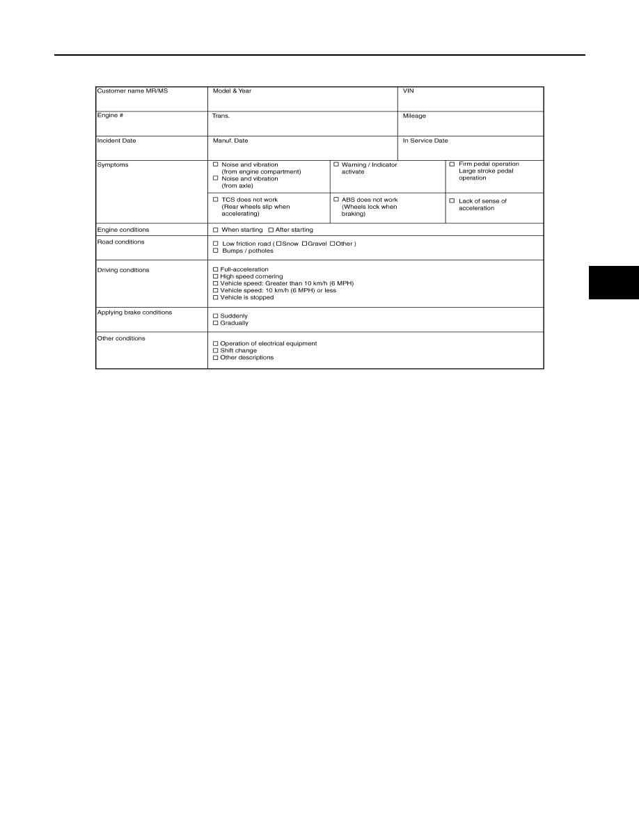
Diagnostic Work Sheet

INFOID:0000000003132854

SFIA3265E

BRC-8

< BASIC INSPECTION >

[VDC/TCS/ABS]

INSPECTION AND ADJUSTMENT

INSPECTION AND ADJUSTMENT

ADDITIONAL SERVICE WHEN REPLACING CONTROL UNIT

ADDITIONAL SERVICE WHEN REPLACING CONTROL UNIT : Description

INFOID:0000000003132855

After replacing the ABS actuator and electric unit (control unit), perform the neutral position adjustment for the
steering angle sensor.

ADDITIONAL SERVICE WHEN REPLACING CONTROL UNIT : Special Repair Re-
quirement

INFOID:0000000003132856

1.

PERFORM THE NEUTRAL POSITION ADJUSTMENT FOR THE STEERING ANGLE SENSOR

Perform the neutral position adjustment for the steering angle sensor.

>> Refer to 

BRC-8, "ADJUSTMENT OF STEERING ANGLE SENSOR NEUTRAL POSITION : Spe-

cial Repair Requirement"

.

ADJUSTMENT OF STEERING ANGLE SENSOR NEUTRAL POSITION

ADJUSTMENT OF STEERING ANGLE SENSOR NEUTRAL POSITION : Description

INFOID:0000000003132857

When doing work that applies to the list below, make sure to adjust neutral position of steering angle sensor
before running vehicle.

×

: Required –: Not required

ADJUSTMENT OF STEERING ANGLE SENSOR NEUTRAL POSITION : Special Re-
pair Requirement

INFOID:0000000003132858

ADJUSTMENT OF STEERING ANGLE SENSOR NEUTRAL POSITION

CAUTION:

To adjust neutral position of steering angle sensor, make sure to use CONSULT-III.
(Adjustment cannot be done without CONSULT-III.)

1.

ALIGN THE VEHICLE STATUS

Stop the vehicle with front wheels in straight-ahead position.

>> GO TO 2.

2.

PERFORM THE NEUTRAL POSITION ADJUSTMENT FOR THE STEERING ANGLE SENSOR

1.

On the CONSULT-III screen, touch "WORK SUPPORT" and “ST ANG SEN ADJUSTMENT" in order.

2.

Touch “START”.

Situation

Adjustment of steering angle sensor neutral position

Removing/Installing ABS actuator and electric unit (control unit)

Replacing ABS actuator and electric unit (control unit)

×

Removing/Installing steering angle sensor

×

Replacing steering angle sensor

×

Removing/Installing steering components

×

Replacing steering components

×

Removing/Installing suspension components

×

Replacing suspension components

×

Change tires to new ones

Tire rotation

Adjusting wheel alignment

×

INSPECTION AND ADJUSTMENT

BRC-9

< BASIC INSPECTION >

[VDC/TCS/ABS]

C

D

E

G

H

I

J

K

L

M

A

B

BRC

N

O

P

CAUTION:

Do not touch steering wheel while adjusting steering angle sensor.

3.

After approximately 10 seconds, touch “END”.
NOTE:
After approximately 60 seconds, it ends automatically.

4.

Turn ignition switch OFF, then turn it ON again.

CAUTION:

Be sure to perform above operation.

>> GO TO 3.

3.

CHECK DATA MONITOR

1.

Run the vehicle with front wheels in straight-ahead position, then stop.

2.

Select “STR ANGLE SIG” in “DATA MONITOR” and check steering angle sensor signal.

Is the steering angle within the specified range?

YES

>> GO TO 4.

NO

>> Perform the neutral position adjustment for the steering angle sensor again, GO TO 1.

4.

ERASE THE SELF-DIAGNOSIS MEMORY

Erase the self-diagnosis memories of the ABS actuator and electric unit (control unit), ECM and ICC.
• ABS actuator and electric unit (control unit): Refer to 

BRC-30, "CONSULT-III Function"

.

• ECM: Refer to 

EC-113, "CONSULT-III Function"

.

• ICC: Refer to 

CCS-24, "CONSULT-III Function (ICC)"

.

Are the memories erased?

YES

>> INSPECTION END

NO

>> Check the items indicated by the self-diagnosis.

STR ANGLE SIG

: 0

±

2.5

°

BRC-10

< FUNCTION DIAGNOSIS >

[VDC/TCS/ABS]

VDC

FUNCTION DIAGNOSIS

VDC

System Diagram

INFOID:0000000003132859

With LDP

Without LDP

JSFIA0227GB

JSFIA0228GB


Content   ..  321  322  323  324   ..