Infiniti EX35. Manual - part 265


  Index      Infiniti     Infiniti EX35 - service repair manual 2008 year


Search            


Content   ..  263  264  265  266   ..


Infiniti EX35. Manual - part 265


AV

AROUND VIEW MONITOR CONTROL UNIT

AV-841

< ECU DIAGNOSIS >

[BOSE AUDIO WITH NAVIGATION]

C

D

E

F

G

H

I

J

K

L

M

B

A

O

P

21

(W)

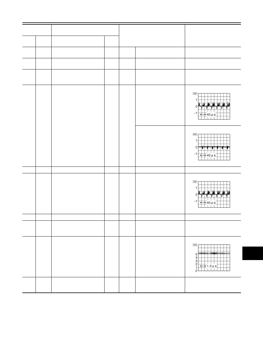
AV communication signal (H)

Input/

Output

22

(B)

AV communication signal (L)

Input/

Output

23

(LG)

24

(G)

Auxiliary infrared LED power 
supply

Output

Ignition 

switch 

ON

“CAMERA” switch is ON or 
shift position is “R”.

5.5 V

27

(W)

Ground

Camera image signal

Output

Ignition 

switch 

ON

At camera image display

Other than camera image 
display

28

Camera image ground

29

(Y)

30

(G)

Side camera passenger side 
image signal

Input

Input

“CAMERA” switch is ON or 
shift position is “R”.

31

Shield

32

(B)

Ground

Side camera passenger side 
ground

Ignition 

switch 

ON

0  V

33

(W)

Ground

Side camera passenger side 
communication signal

Input/

Output

Ignition 

switch 

ON

“CAMERA” switch is ON or 
shift position is “R”.

34

(R)

Ground

Side camera passenger side 
power supply

Output

Ignition 

switch 

ON

“CAMERA” switch is ON or 
shift position is “R”.

6.0 V

Terminal

(Wire color)

Description

Condition

Reference value

(Approx.)

+

Signal name

Input/

Output

JSNIA0834GB

JSNIA0835GB

JSNIA0834GB

JSNIA0836GB

AV-842

< ECU DIAGNOSIS >

[BOSE AUDIO WITH NAVIGATION]

AROUND VIEW MONITOR CONTROL UNIT

35

(L)

Ground

Rear camera communication 
signal

Input/

Output

Ignition 

switch 

ON

“CAMERA” switch is ON or 
shift position is “R”.

36

(BR)

Ground

Rear camera power supply

Output

Ignition 

switch 

ON

“CAMERA” switch is ON or 
shift position is “R”.

6.0 V

37

Shield

38

(R)

Ground

Rear camera ground

Ignition 

switch 

ON

0  V

39

(Y)

40

(W)

Rear camera image signal

Input

Ignition 

switch 

ON

“CAMERA” switch is ON or 
shift position is “R”.

41

(Y)

42

(G)

Front camera image signal

Input

Ignition 

switch 

ON

“CAMERA” switch is ON or 
shift position is “R”.

43

Shield

44

(B)

Ground

Front camera ground

Ignition 

switch 

ON

0  V

45

(W)

Ground

Front camera communication 
signal

Input/

Output

Ignition 

switch 

ON

“CAMERA” switch is ON or 
shift position is “R”.

46

(R)

Ground

Front camera power supply

Output

Ignition 

switch 

ON

“CAMERA” switch is ON or 
shift position is “R”.

6.0 V

47

(L)

Ground

Side camera driver side com-
munication signal

Input/

Output

Ignition 

switch 

ON

“CAMERA” switch is ON or 
shift position is “R”.

Terminal

(Wire color)

Description

Condition

Reference value

(Approx.)

+

Signal name

Input/

Output

JSNIA0836GB

JSNIA0834GB

JSNIA0834GB

JSNIA0836GB

JSNIA0836GB

AV

AROUND VIEW MONITOR CONTROL UNIT

AV-843

< ECU DIAGNOSIS >

[BOSE AUDIO WITH NAVIGATION]

C

D

E

F

G

H

I

J

K

L

M

B

A

O

P

Wiring Diagram - BOSE AUDIO WITH NAVIGATION AND AROUND VIEW MONITOR 
-

INFOID:0000000003737138

Click here to view the eWD.
NOTE:

48

(BR)

Ground

Side camera driver side power 
supply

Output

Ignition 

switch 

ON

“CAMERA” switch is ON or 
shift position is “R”.

6.0 V

49

Shield

50

(R)

Ground

Side camera driver side 
ground

Ignition 

switch 

ON

0  V

51

(Y)

52

(W)

Side camera driver side image 
signal

Input

Ignition 

switch 

ON

“CAMERA” switch is ON or 
shift position is “R”.

Terminal

(Wire color)

Description

Condition

Reference value

(Approx.)

+

Signal name

Input/

Output

JSNIA0834GB

AV-844

< ECU DIAGNOSIS >

[BOSE AUDIO WITH NAVIGATION]

AROUND VIEW MONITOR CONTROL UNIT

The name MULTIFUNCTION SWITCH indicates the integration of PRESET SWITCH and MULTIFUNCTION
SWITCH virtually.

JCNWM0793GB


Content   ..  263  264  265  266   ..