Infiniti EX35. Manual - part 218
 

  Index      Infiniti     Infiniti EX35 - service repair manual 2008 year


Search            


Content   ..  216  217  218  219   ..


Infiniti EX35. Manual - part 218


AV

DISPLAY UNIT

AV-653

< ECU DIAGNOSIS >

[BOSE AUDIO WITH NAVIGATION]

C

D

E

F

G

H

I

J

K

L

M

B

A

O

P

DISPLAY UNIT

Reference Value

INFOID:0000000003160744

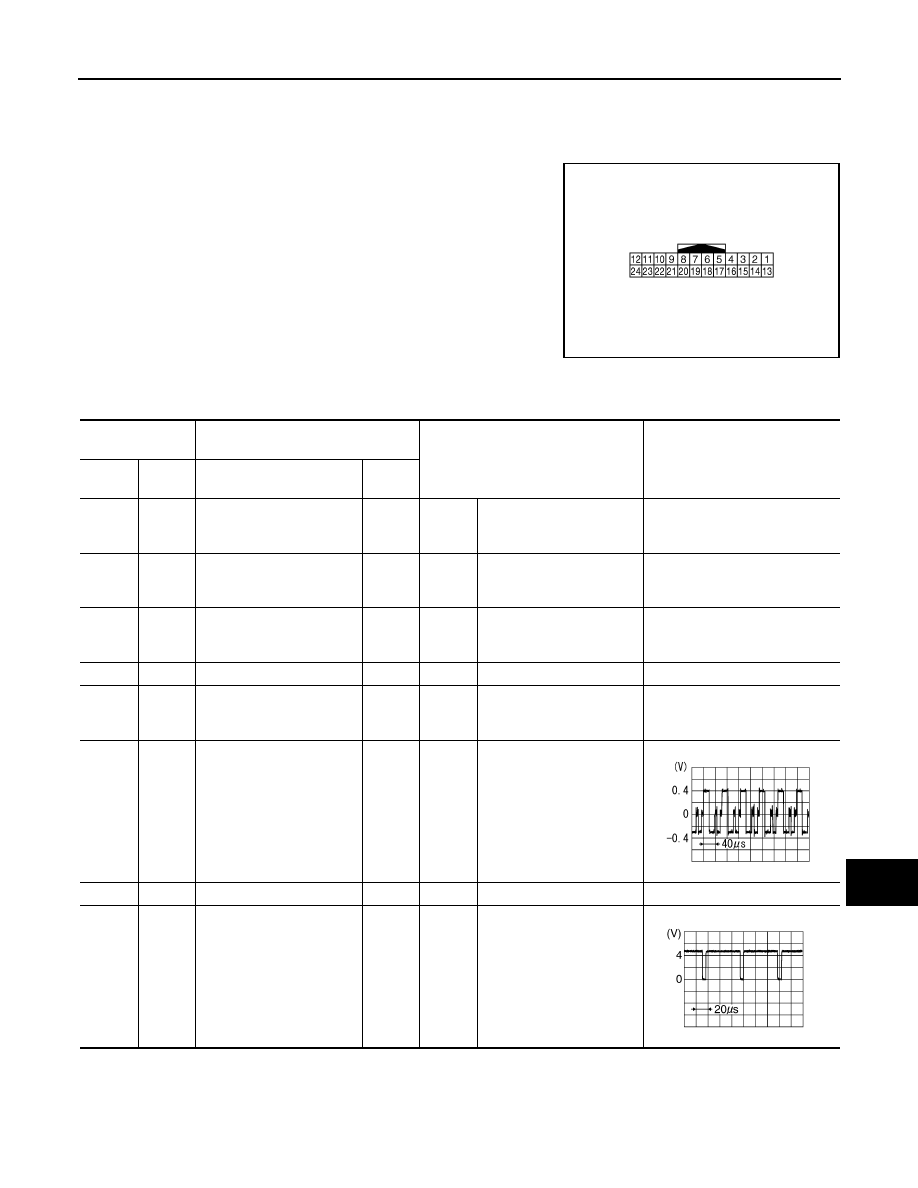
TERMINAL LAYOUT

PHYSICAL VALUES

JPNIA0006ZZ

Terminal

(Wire color)

Description

Condition

Reference value

(Approx.)

+

–

Signal name

Input/

Output

1

(B)

Ground

Ground

—

Ignition 

switch 

ON 

—

0  V

2

(Y)

Ground

Battery power supply

Input

Ignition 

switch 

OFF

—

Battery voltage

3

(V)

Ground

ACC power supply

Input

Ignition 

switch 

ACC

—

Battery voltage

4

—

Shield

—

—

—

—

5

(R)

Ground

AUX image ground

—

Ignition 

switch 

ON

—

0  V

6

(W)

Ground

RGB signal (G: green)

Input

Ignition 

switch 

ON

Start confirmation/adjust-
ment mode, and then dis-
play color bar by 
selecting“Color Spectrum 
Bar” on DISPLAY DIAGNO-
SIS screen.

7

—

Shield

—

—

—

—

8

(R)

Ground

Horizontal synchronizing 
(HP) signal

Output

Ignition 

switch 

ON

—

SKIB2236J

SKIB3601E

AV-654

< ECU DIAGNOSIS >

[BOSE AUDIO WITH NAVIGATION]

DISPLAY UNIT

9

(B)

Ground

RGB area (YS) signal

Input

Ignition 

switch 

ON

At RGB image display

5.0 V

At rear view camera image 
display

11

(BR)

Ground

Communication signal
(CONT

→

DISP)

Input

Ignition 

switch 

ON

When adjusting display 
brightness.

12

(W)

Ground

Camera image signal

Input

Ignition 

switch 

ON

At rear view camera image 
display

13

(B)

Ground

Ground

—

Ignition 

switch 

ON

—

0  V

14

—

Shield

—

—

—

—

15

(G)

Ground

AUX image signal

Input

Ignition 

switch 

ON

AUX image display

17

(B)

Ground

RGB signal (R: red)

Input

Ignition 

switch 

ON

Start confirmation/adjust-
ment mode, and then dis-
play color bar by selecting 
“Color Spectrum Bar” on 
DISPLAY DIAGNOSIS 
screen.

18

(R)

Ground

RGB signal (B: blue)

Input

Ignition 

switch 

ON

Start confirmation/adjust-
ment mode, and then dis-
play color bar by 
selecting“Color Spectrum 
Bar” on DISPLAY DIAGNO-
SIS screen.

Terminal

(Wire color)

Description

Condition

Reference value

(Approx.)

+

–

Signal name

Input/

Output

PKIB4948J

PKIB5039J

SKIB2251J

SKIB2251J

SKIB2238J

SKIB2237J

AV

DISPLAY UNIT

AV-655

< ECU DIAGNOSIS >

[BOSE AUDIO WITH NAVIGATION]

C

D

E

F

G

H

I

J

K

L

M

B

A

O

P

WITHOUT REAR VIEW MONITOR AND AROUND VIEW MONITOR

WITHOUT REAR VIEW MONITOR AND AROUND VIEW MONITOR : Wiring Diagram 
- BOSE AUDIO WITH NAVIGATION -

INFOID:0000000003737128

Click here to view the eWD.
NOTE:

19

(G)

Ground

RGB synchronizing signal

Input

Ignition 

switch 

ON

—

20

(W)

Ground

Vertical synchronizing (VP) 
signal

Output

Ignition 

switch 

ON

—

21

—

Shield

—

—

—

—

22

(Y)

Ground

Communication signal
(DISP

→

CONT)

Output

Ignition 

switch 

ON

When adjusting display 
brightness.

23

—

Shield

—

—

—

—

Terminal

(Wire color)

Description

Condition

Reference value

(Approx.)

+

–

Signal name

Input/

Output

SKIB3603E

SKIB3598E

PKIB5039J

AV-656

< ECU DIAGNOSIS >

[BOSE AUDIO WITH NAVIGATION]

DISPLAY UNIT

The name MULTIFUNCTION SWITCH indicates the integration of PRESET SWITCH and MULTIFUNCTION
SWITCH virtually.

JCNWM0761GB


Content   ..  216  217  218  219   ..