Infiniti EX35. Manual - part 201
AV
SIDE CAMERA LH IMAGE SIGNAL CIRCUIT
AV-585
< COMPONENT DIAGNOSIS >
[BOSE AUDIO WITH NAVIGATION]
C
D
E
F
G
H
I
J
K
L
M
B
A
O
P
4.
Check continuity between around view monitor control unit harness connector and ground.
Is inspection result normal?
YES
>> GO TO 4.
NO
>> Repair harness or connector.
4.
CHECK SIDE CAMERA LH IMAGE SIGNAL
1.
Connect around view monitor control unit connector and door mirror (driver side) connector.
2.
Turn ignition switch ON.
3.
Check signal between around view monitor control unit harness connector.
Is inspection result normal?
YES
>> Replace around view monitor control unit.
NO
>> Replace side camera LH.
Around view monitor control
unit
Door mirror (driver side)
Continuity
Connector
Terminals
Connector
Terminals
B45
51
D3
5
Existed
52
17
Around view monitor control
unit
Ground
Continuity
Connector
Terminals
B45
51, 52
Not existed
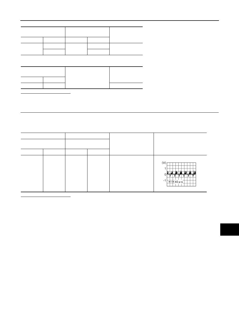
(+)
(
−
)
Condition
Reference value
Around view monitor control
unit
Around view monitor control
unit
Connector
Terminal
Connector
Terminal
B45
51
B45
52
“CAMERA” switch is ON or
shift position is “R”.
JSNIA0834GB