Content .. 1448 1449 1450 1451 ..
Infiniti EX35. Manual - part 1450
TM-188
< ON-VEHICLE REPAIR >
[5AT: RE5R05A]
A/T FLUID COOLER TUBE
A/T FLUID COOLER TUBE
2WD
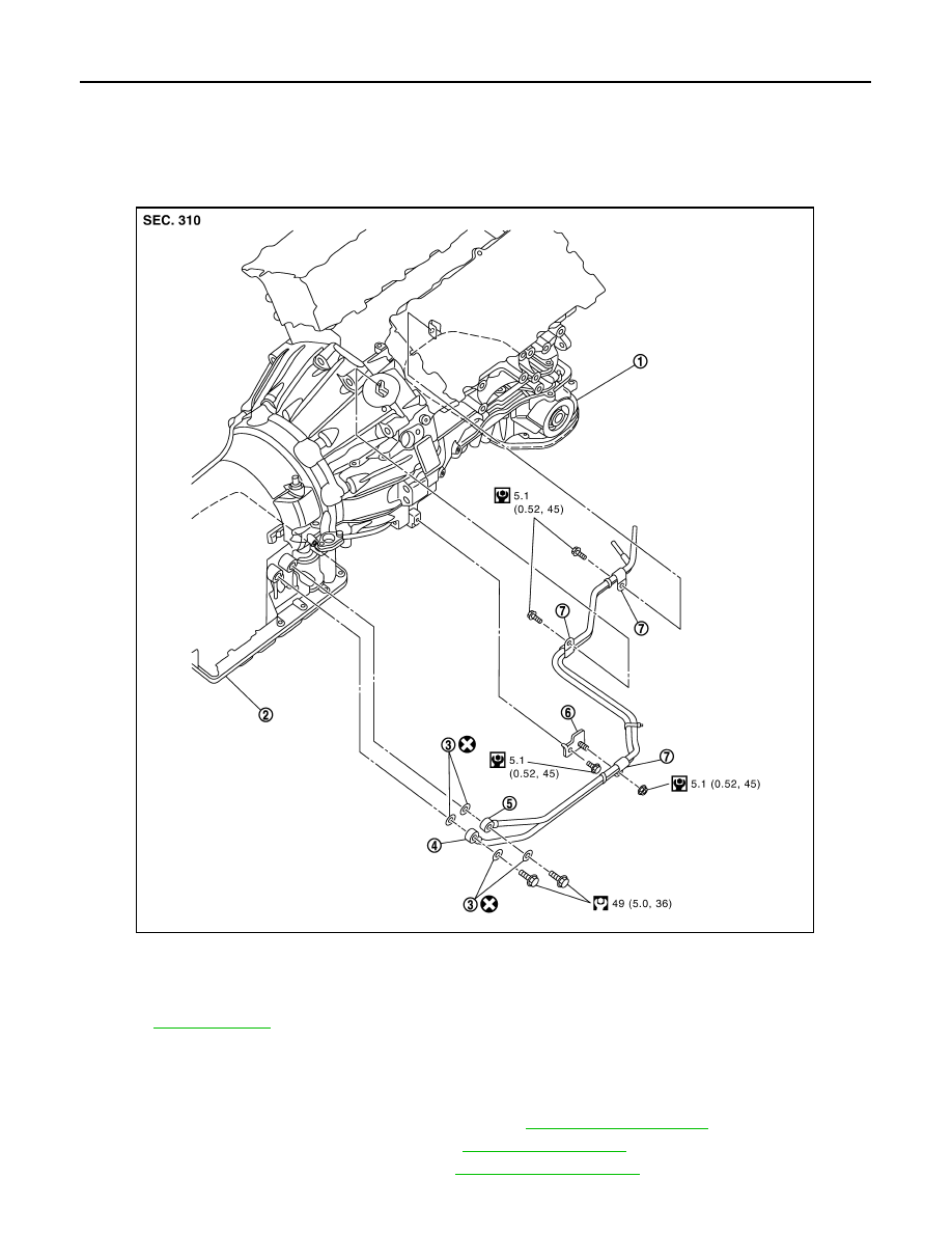
2WD : Exploded View
INFOID:0000000003130633
2WD : Removal and Installation
INFOID:0000000003130634
REMOVAL
1.
Remove the engine lower cover with power tool. Refer to
2.
Remove the exhaust mounting bracket. Refer to
.
3.
Remove the suspension member stay. Refer to
1.
Engine assembly
2.
A/T assembly
3.
Copper washer
4.
A/T fluid cooler tube
5.
A/T fluid cooler tube
6.
Bracket
7.
Clip
Refer to
for symbols in the figure.
JPDIA0554GB