Content .. 1403 1404 1405 1406 ..
Infiniti EX35. Manual - part 1405
TM-8
< FUNCTION DIAGNOSIS >
[5AT: RE5R05A]
A/T CONTROL SYSTEM
FUNCTION DIAGNOSIS
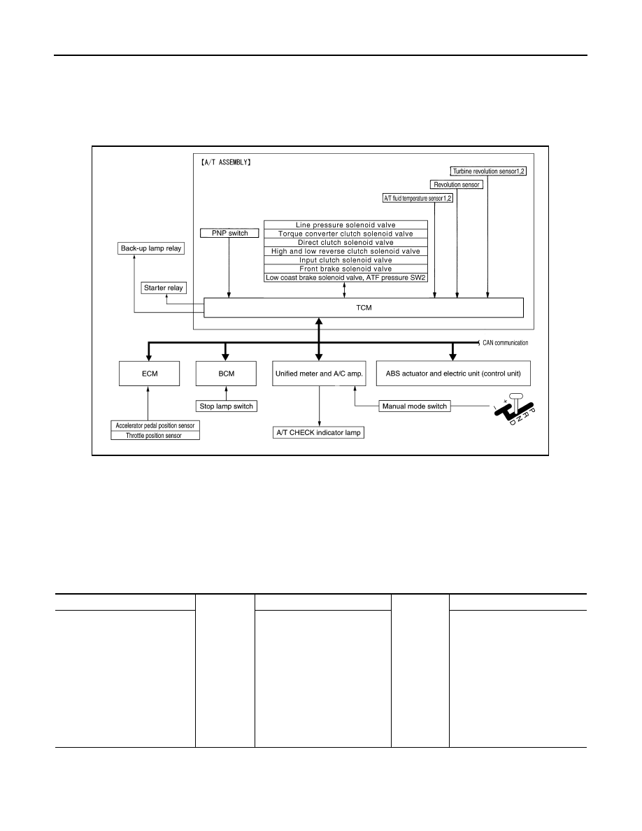
A/T CONTROL SYSTEM
System Diagram
INFOID:0000000003130457
System Description
INFOID:0000000003130458
The A/T senses vehicle operating conditions through various sensors or signals. It always controls the opti-
mum shift position and reduces shifting and lock-up shocks.
TCM FUNCTION
The function of the TCM is to:
• Receive input signals transmitted from various switches and sensors.
• Determine required line pressure, shifting point, lock-up operation, engine brake operation, etc.
• Transmit required output signals to the respective solenoids.
Input/Output Signal of TCM
JSDIA0122GB
SENSORS (or SIGNALS)
⇒
TCM
⇒
ACTUATORS
PNP switch
Accelerator pedal position signal
Closed throttle position signal
Wide open throttle position signal
Engine speed signal
A/T fluid temperature sensor
Revolution sensor
Vehicle speed signal
Manual mode switch signal
Stop lamp switch signal
Turbine revolution sensor
ATF pressure switch
Shift control
Line pressure control
Lock-up control
Engine brake control
Timing control
Fail-safe control
Self-diagnosis
CONSULT-III communication
line
Duet-EA control
CAN system
Input clutch solenoid valve
Direct clutch solenoid valve
Front brake solenoid valve
High and low reverse clutch sole-
noid valve
Low coast brake solenoid valve
Torque converter clutch solenoid
valve
Line pressure solenoid valve
A/T CHECK indicator lamp
Back-up lamp relay
Starter relay