Infiniti EX35. Manual - part 1387


  Index      Infiniti     Infiniti EX35 - service repair manual 2008 year


Search            


Content   ..  1385  1386  1387  1388   ..


Infiniti EX35. Manual - part 1387


STEERING GEAR AND LINKAGE

ST-29

< ON-VEHICLE REPAIR >

C

D

E

F

H

I

J

K

L

M

A

B

ST

N

O

P

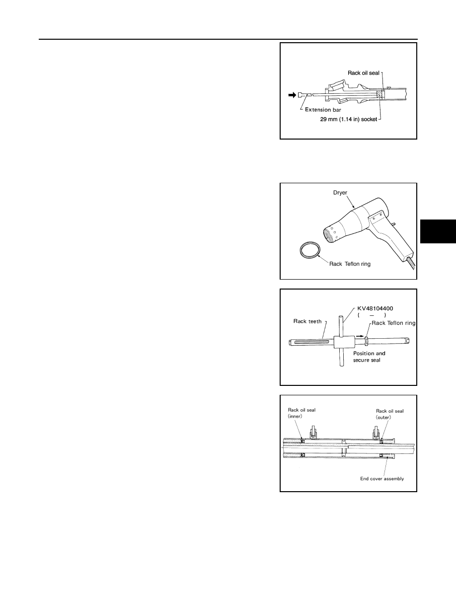
14. Push rack oil seal inside with a 29 mm (1.14 in) socket and an

extension bar to push out rack oil seal (inner side) from gear
housing assembly.

CAUTION:

Never damage gear housing assembly and cylinder inner
wall. Gear housing assembly must be replaced if damaged
because it may cause fluid leakage.

ASSEMBLY

1.

Heat rack Teflon ring to approximately 40

°

C (104

°

F) with a dryer. Assemble it to mounting groove of rack

assembly.

CAUTION:

Never reuse rack Teflon ring.

2.

Install the Teflon ring correcting tool [SST: KV48104400 (

)] from tooth side of rack to fit rack Teflon ring on rack. Com-

press the ring with tool.

3.

Apply recommended grease to rack oil seal, and then install
rack oil seal in the following procedure. Then assemble rack
assembly to gear housing assembly.

CAUTION:

• Install rack oil seal in a direction so that the lip of inner oil

seal and the lip of outer oil seal face each other.

• Never damage retainer sliding surface by rack assembly.

Replace gear housing assembly if damaged.

• Never damage gear housing assembly inner wall by rack

assembly. Gear housing assembly must be replaced if
damaged because it may cause fluid leakage.

• Never reuse rack oil seal.

SGIA0179E

SGIA0153E

SGIA0154E

SGIA0205E

ST-30

< ON-VEHICLE REPAIR >

STEERING GEAR AND LINKAGE

a.

Wrap an OHP sheet [approximately 70 mm (2.76 in) 

×

 100 mm

(3.94 in)]. Around rack assembly teeth to avoid damaging rack
oil seal (inner). Install rack oil seal over sheet. Then, pull OHP
sheet along with rack oil seal until they pass rack assembly
teeth, and remove OHP sheet.

b.

Insert rack oil seal (inner) into rack assembly piston (rack Teflon
ring).

c.

Push retainer to adjusting screw side by hand, and move the
rack assembly inside the gear housing assembly so that the
rack oil seal (inner) can be pressed against the gear housing
assembly.

d.

Wrap an OHP sheet [approximately 70 mm (2.76 in) 

×

 100 mm

(3.94 in)]. Around the edge to avoid damaging rack oil seal
(outer). Install rack oil seal over sheet. Then, pull oil seal along
with OHP sheet until they pass rack edge, and remove OHP
sheet.

e.

Install end cover assembly to rack edge, and move rack oil seal
(outer) until it contacts with gear housing assembly.

4.

Tighten end cover assembly to specified torque using a 36 mm
(1.42 in) open head (suitable tool).

CAUTION:

Never damage rack assembly. Replace it if damaged
because it may cause fluid leakage.

5.

Crimp gear housing assembly at one point using a punch as
shown in the figure so as to prevent end cover assembly from
getting loose after tightening end cover assembly.

6.

Apply recommended fluid to O-ring, and then install O-ring to
gear housing assembly.

7.

Install gear-sub assembly to gear housing assembly.

CAUTION:

In order to protect oil seal from any damage, insert gear-
sub assembly straightly.

8.

Install inner socket to gear housing assembly with the following
procedure.

SGIA0155E

SGIA0671E

SGIA0157E

SST081B

SGIA0871E

STEERING GEAR AND LINKAGE

ST-31

< ON-VEHICLE REPAIR >

C

D

E

F

H

I

J

K

L

M

A

B

ST

N

O

P

a.

Apply thread sealant into the thread of inner socket.
Use Genuine Silicone RTV or equivalent. Refer to 

GI-15, "Recommended Chemical Products and

Sealants"

.

9.

Screw inner socket into rack part and tighten at the specified torque.

10. Decide on the neutral position of the rack stroke (L).

11. Install rear cover cap to gear sub-assembly.

CAUTION:

Make sure that the projection of rear cover cap is aligned
with the marking position of gear housing assembly.

12. Apply recommended thread locking sealant to the thread (2

turns thread), and then screw in the adjusting screw until it
reaches height “H” from gear housing assembly measured
before disassembling.

13. Move rack assembly 10 strokes throughout the full stroke so that

the parts can fit with each other.

14. Adjust pinion rotating torque with the following procedure.

a.

Measure pinion rotating torque within 

±

180

°

 of neutral position

of the rack assembly using Tools. Stop the gear at the point
where highest torque is read.

b.

Loosen adjusting screw and retighten to 5.4 N·m (0.55 kg-m, 48
in-lb), and then loosen by 20 to 40

°

.

c.

Measure pinion rotating torque using tools to make sure that the
measured value is within the standard. Readjust if the value is
outside the standard. Replace steering gear assembly, if the
value is outside the standard after readjusting, or adjusting
screw rotating torque is 5 N·m (0.51 kg-m, 44 in-lb) or less.

d.

Apply recommended liquid gasket to inner socket and turn pinion fully to left with inner socket installed to
gear housing assembly.

Standard

L

: Refer to 

ST-54, "Rack 

Stroke"

.

SGIA0877E

SGIA0624E

A: Preload gauge [SST: ST3127S000 (J-25765-A)]

B: Preload adapter [SST: KV48103400 (

)]

SGIA1383E

Pinion rotating torque

Around neutral position 
(within

±

100

°

) average “A”

: 2.27 – 3.05 N·m (0.24 – 
0.31 kg-m, 20 – 26 in-lb)

Maximum variation “B”

: 0.98 N·m (0.10 kg-m, 9.0 
in-lb)

SGIA0936E

ST-32

< ON-VEHICLE REPAIR >

STEERING GEAR AND LINKAGE

e.

Install dial gauge at 5 mm (0.20 in) (L) from the edge of gear
housing assembly (1), and tooth point.

f.

Measure vertical movement of rack assembly when pinion is
turned clockwise with torque of 19.6 N·m (2.0 kg-m, 14 ft-lb).
Readjust adjusting screw angle if the measured value is outside
the standard.

• If reading is outside of the specification, readjust screw angle

with adjusting screw.

CAUTION:

• If reading is still outside of specification, or if the rotating torque of adjusting screw is less

than 5 N·m (0.51 kg-m, 44 in-lb), replace steering gear assembly.

• Never turn adjusting screw more than twice.
• Replace steering gear assembly when adjusting screw is removed or turned more than twice.

15. Install large end of boot to gear housing assembly.

16. Install small end of boot to inner socket boot mounting groove.
17. Install boot clamp to boot small end.

18. Install boot clamp to the large side of boot with the following procedure.

CAUTION:

Never reuse boot clamp.

a.

Tighten large side of boot with boot clamp (stainless wire).

b.

Wrap clamp around boot groove for two turns. Insert a flat-
bladed screwdriver in loops on both ends of wire. Twist 4 to 4.5
turns while pulling them with force of approximately 98 N (10 kg,
22 lb).

c.

Twist boot clamp as shown. Pay attention to relationship
between winding and twisting directions.

Vertical movement

: 0.265 mm (0.0104 in)

JSGIA0104ZZ

SGIA1325E

Wire length (L)

: 370 mm (14.57 in)

SGIA0163E

SGIA0164E


Content   ..  1385  1386  1387  1388   ..