Content .. 1333 1334 1335 1336 ..
Infiniti EX35. Manual - part 1335
SN
SONAR CONTROL UNIT
SN-31
< ECU DIAGNOSIS >
C
D
E
F
G
H
I
J
K
L
M
B
A
O
P
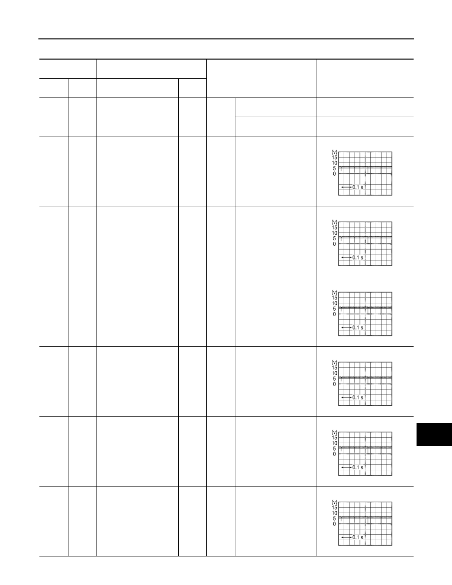
PHYSICAL VALUES
Terminal No.
(Wire color)
Description
Condition
Value
(Approx.)
+
–
Signal name
Input/
Output
2
(R)
Ground
Cancel switch signal
Input
Ignition
switch
ON
Turns ON while pressing
sonar cancel switch ON.
0 V
Other than while pressing
sonar cancel switch ON.
12.0 V
3
(R)
12
(B)
Corner sensor signal front
LH
Input
Ignition
switch
ON
Other than shift position in
P position.
4
(W)
12
(B)
Corner sensor signal front
RH
Input
Ignition
switch
ON
Other than shift position in
P position.
5
(W)
12
(B)
Corner sensor signal rear
LH
Input
Ignition
switch
ON
Shift position in R position.
6
(L)
12
(B)
Corner sensor signal rear
RH
Input
Ignition
switch
ON
Selector lever in R position.
7
(G)
12
(B)
Center sensor signal rear
LH
Input
Ignition
switch
ON
Selector lever in R position.
8
(Y)
12
(B)
Center sensor signal rear
RH
Input
Ignition
switch
ON
Selector lever in R position.
SKIB8942E
SKIB8942E
SKIB8942E
SKIB8942E
SKIB8942E
SKIB8942E