Content .. 1279 1280 1281 1282 ..
Infiniti EX35. Manual - part 1281
SEC-20
< FUNCTION DIAGNOSIS >
[INTELLIGENT KEY SYSTEM]
VEHICLE SECURITY SYSTEM
VEHICLE SECURITY SYSTEM
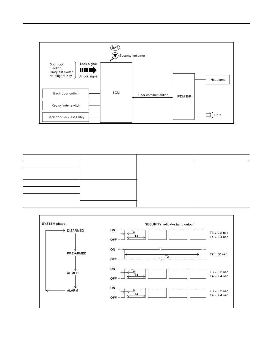
System Diagram
INFOID:0000000003586649
System Description
INFOID:0000000003586650
INPUT/OUTPUT SIGNAL CHART
OPERATION FLOW
SETTING THE VEHICLE SECURITY SYSTEM
Initial Condition
• Ignition switch is in OFF position.
Disarmed Phase
JMKIA1873GB
Switch
Input signal to BCM
BCM system
Actuator
All door switch
Open or close
Vehicle security system
• IPDM E/R
• Head lamp
• Horn
• Security indicator lamp
Back door lock assembly (door
switch)
Door key cylinder switch
Lock or unlock
Door request switch
Intelligent Key
Panic alarm
PIIA1367E