Content .. 1147 1148 1149 1150 ..
Infiniti EX35. Manual - part 1149
PCS
BCM (BODY CONTROL MODULE)
PCS-97
< ECU DIAGNOSIS >
[POWER DISTRIBUTION SYSTEM]
C
D
E
F
G
H
I
J
K
L
B
A
O
P
N
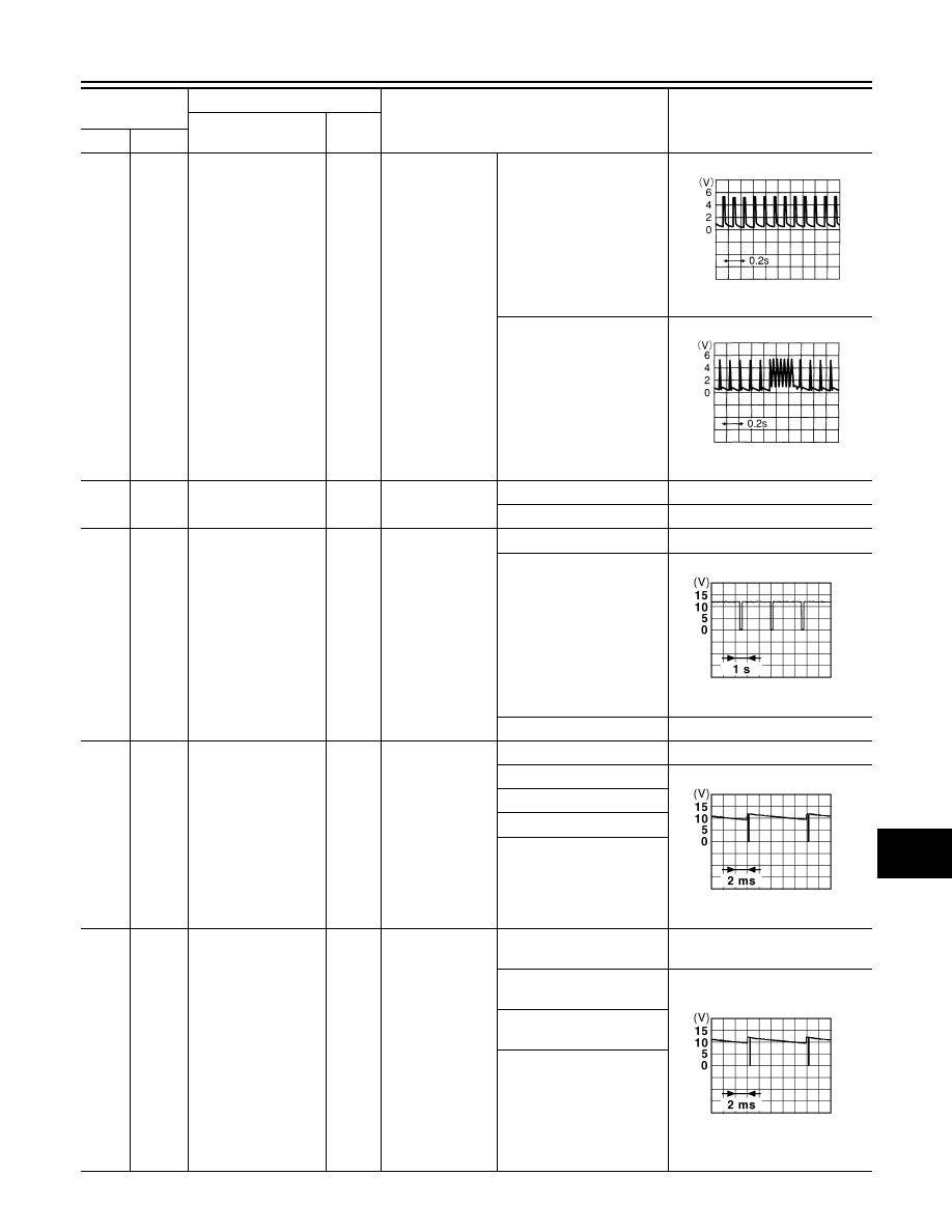
139
(L)
Ground
Tire pressure receiv-
er signal
Input/
Output
Ignition switch
ON
Standby state
When receiving the signal
from the transmitter
140
(GR)
Ground
Selector lever P/N
position signal
Input
Selector lever
P or N position
Battery voltage
Except P and N positions
0 V
141
(G)
Ground
Security indicator sig-
nal
Output
Security indicator
ON
0 V
Blinking
11.3 V
OFF
Battery voltage
142
(O)
Ground
Combination switch
OUTPUT 5
Output
Combination
switch
(Wiper intermit-
tent dial 4)
All switch OFF
0 V
Lighting switch 1ST
10.7 V
Lighting switch HI
Lighting switch 2ND
Turn signal switch RH
143
(P)
Ground
Combination switch
OUTPUT 1
Output
Combination
switch
All switch OFF
(Wiper intermittent dial 4)
0 V
Front wiper switch HI
(Wiper intermittent dial 4)
10.7 V
Rear wiper switch INT
(Wiper intermittent dial 4)
Any of the conditions below
with all switch OFF
• Wiper intermittent dial 1
• Wiper intermittent dial 2
• Wiper intermittent dial 3
• Wiper intermittent dial 6
• Wiper intermittent dial 7
Terminal No.
(Wire color)
Description
Condition
Value
(Approx.)
Signal name
Input/
Output
+
–
OCC3881D
OCC3880D
JPMIA0014GB
JPMIA0031GB
JPMIA0032GB