Infiniti EX35. Manual - part 1126


  Index      Infiniti     Infiniti EX35 - service repair manual 2008 year


Search            


Content   ..  1124  1125  1126  1127   ..


Infiniti EX35. Manual - part 1126


PCS

RELAY CONTROL SYSTEM

PCS-5

< FUNCTION DIAGNOSIS >

[IPDM E/R]

C

D

E

F

G

H

I

J

K

L

B

A

O

P

N

NOTE:

BCM controls the starter relay.
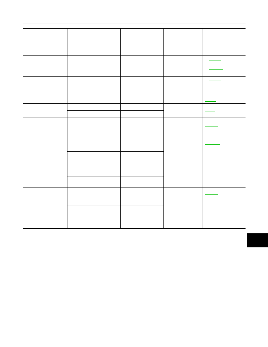
Control relay

Input/output

Transmit unit

Control part

Reference page

• Headlamp low relay
• Headlamp high relay

• Low beam request signal
• High beam request signal

BCM (CAN)

• Headlamp low
• Headlamp high

EXL-11

(Xenon headlamp)

EXL-212

(Halogen headlamp)

Front fog lamp relay

Front fog light request signal

BCM (CAN)

Front fog lamp

EXL-24

(Xenon headlamp)

EXL-212

(Halogen headlamp)

Tail lamp relay

Position light request signal

BCM (CAN)

• Parking  lamp
• Side marker lamp
• License plate lamp
• Tail  lamp

EXL-28

(Xenon headlamp)

EXL-225

(Halogen headlamp)

Illuminations

INL-12

• Front wiper relay
• Front wiper high relay

Front wiper request signal

BCM (CAN)

Front wiper

WW-5

Front wiper auto stop signal

Front wiper motor

• Horn  relay  1
• Horn  relay  2

• Theft warning horn request 

signal

• Horn reminder signal

BCM (CAN)

• Horn (low)
• Horn (high)

SEC-20

• Starter relay

NOTE

• Starter control relay

Starter control relay signal

BCM (CAN)

Starter motor

SEC-105

,

SEC-103

Steering lock unit condition 
signal

Steering lock unit

Starter relay control signal

TCM

Steering lock relay

Steering lock relay signal

BCM (CAN)

Steering lock unit

SEC-97

Steering lock unit condition 
signal

Steering lock unit

Control device (Detention 
switch) signal

Control device (Deten-
tion switch)

A/C relay

A/C compressor request sig-
nal

ECM (CAN)

A/C compressor
(magnet clutch)

HAC-55

Ignition relay

Ignition switch ON signal

BCM (CAN)

Ignition relay 

PCS-17

Vehicle speed signal

Unified meter and A/C 
amp. (CAN)

Push-button ignition switch 
signal

Push-button ignition 
switch

PCS-6

< FUNCTION DIAGNOSIS >

[IPDM E/R]

RELAY CONTROL SYSTEM

Component Parts Location

INFOID:0000000003131984

1.

IPDM E/R

A.

Engine room dash panel (RH)

JPMIA0951ZZ

PCS

POWER CONTROL SYSTEM

PCS-7

< FUNCTION DIAGNOSIS >

[IPDM E/R]

C

D

E

F

G

H

I

J

K

L

B

A

O

P

N

POWER CONTROL SYSTEM

System Diagram

INFOID:0000000003131985

System Description

INFOID:0000000003131986

COOLING FAN CONTROL

IPDM E/R outputs pulse duty signal (PWM signal) to the cooling fan control module according to the status of
the cooling fan speed request signal received from ECM via CAN communication. Refer to 

EC-66, "System

Diagram"

.

ALTERNATOR CONTROL

IPDM E/R outputs power generation command signal (PWM signal) to the alternator according to the status of
the power generation command value signal received from ECM via CAN communication. Refer to 

CHG-8,

"System Diagram"

.

Component Parts Location

INFOID:0000000003673975

JSMIA0004GB

1.

IPDM E/R

A.

Engine room dash panel (RH)

JPMIA0951ZZ

PCS-8

< FUNCTION DIAGNOSIS >

[IPDM E/R]

SIGNAL BUFFER SYSTEM

SIGNAL BUFFER SYSTEM

System Diagram

INFOID:0000000003131988

System Description

INFOID:0000000003131989

• IPDM E/R reads the status of the oil pressure switch and transmits the oil pressure switch signal to BCM via

CAN communication. Refer to 

MWI-24, "WARNING LAMPS/INDICATOR LAMPS : System Diagram"

.

• IPDM E/R reads the status of the hood switch and transmits the hood switch signal to BCM via CAN commu-

nication. Refer to 

SEC-114, "Description"

.

• IPDM E/R receives the rear window defogger control signal from BCM via CAN communication and trans-

mits it to ECM and AV control unit via CAN communication. Refer to 

DEF-4, "System Diagram"

.

Component Parts Location

INFOID:0000000003674193

JPMIA0952GB

1.

IPDM E/R

A.

Engine room dash panel (RH)

JPMIA0951ZZ


Content   ..  1124  1125  1126  1127   ..