Infiniti EX35. Manual - part 111
AV
RGB (G: GREEN) SIGNAL CIRCUIT
AV-225
< COMPONENT DIAGNOSIS >
[BOSE AUDIO WITHOUT NAVIGATION]
C
D
E
F
G
H
I
J
K
L
M
B
A
O
P
RGB (G: GREEN) SIGNAL CIRCUIT
Description
INFOID:0000000003544767
Transmit the image displayed with AV control unit with RGB signal to the display unit.
Diagnosis Procedure
INFOID:0000000003544768
1.
CHECK CONTINUITY RGB (G: GREEN) SIGNAL CIRCUIT
1.
Turn ignition switch OFF.
2.
Disconnect display unit connector and AV control unit connector.
3.
Check continuity between display unit harness connector and AV control unit harness connector.
4.
Check continuity between display unit harness connector and ground.
Is the inspection result normal?
YES
>> GO TO 2.
NO
>> Repair harness or connector.
2.
CHECK RGB (G: GREEN) SIGNAL
1.
Connect display unit connector and AV control unit connector.
2.
Turn ignition switch ON.
3.
Check signal between display unit harness connector and ground.
Is the inspection result normal?
YES
>> Replace display unit.
NO
>> Replace AV control unit.
Display unit
AV control unit
Continuity
Connector
Terminal
Connector
Terminal
M71
6
M83
39
Existed
Display unit
Ground
Continuity
Connector
Terminal
M71
6
Not existed
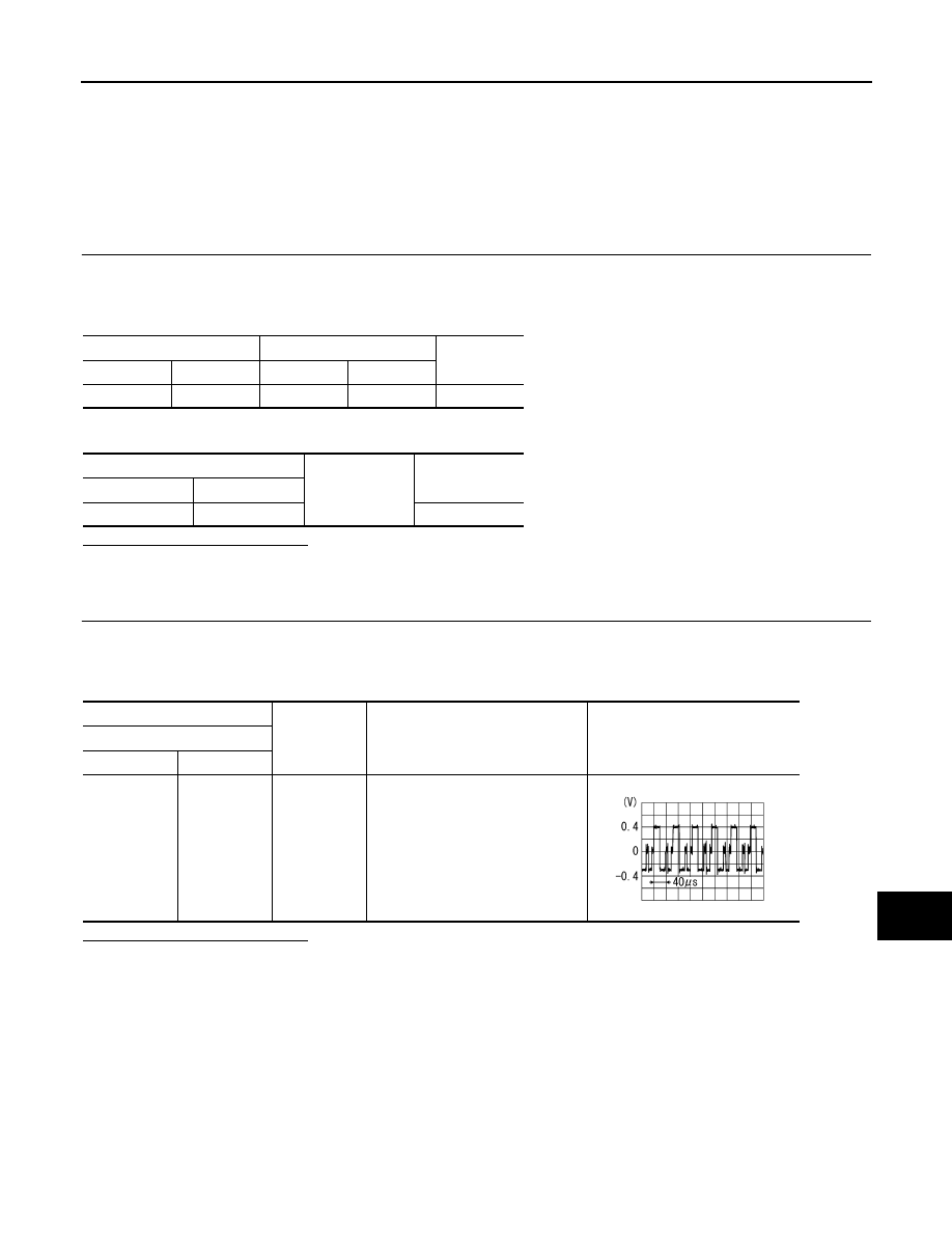
(+)
(
−
)
Condition
Reference value
Display unit
Connector
Terminal
M71
6
Ground
Start confirmation/adjustment
mode, and then display color bar by
selecting “Color Spectrum Bar” on
DISPLAY DIAGNOSIS screen.
SKIB2236J