Content .. 1096 1097 1098 1099 ..
Infiniti EX35. Manual - part 1098
MWI-70
< COMPONENT DIAGNOSIS >
CLOCK
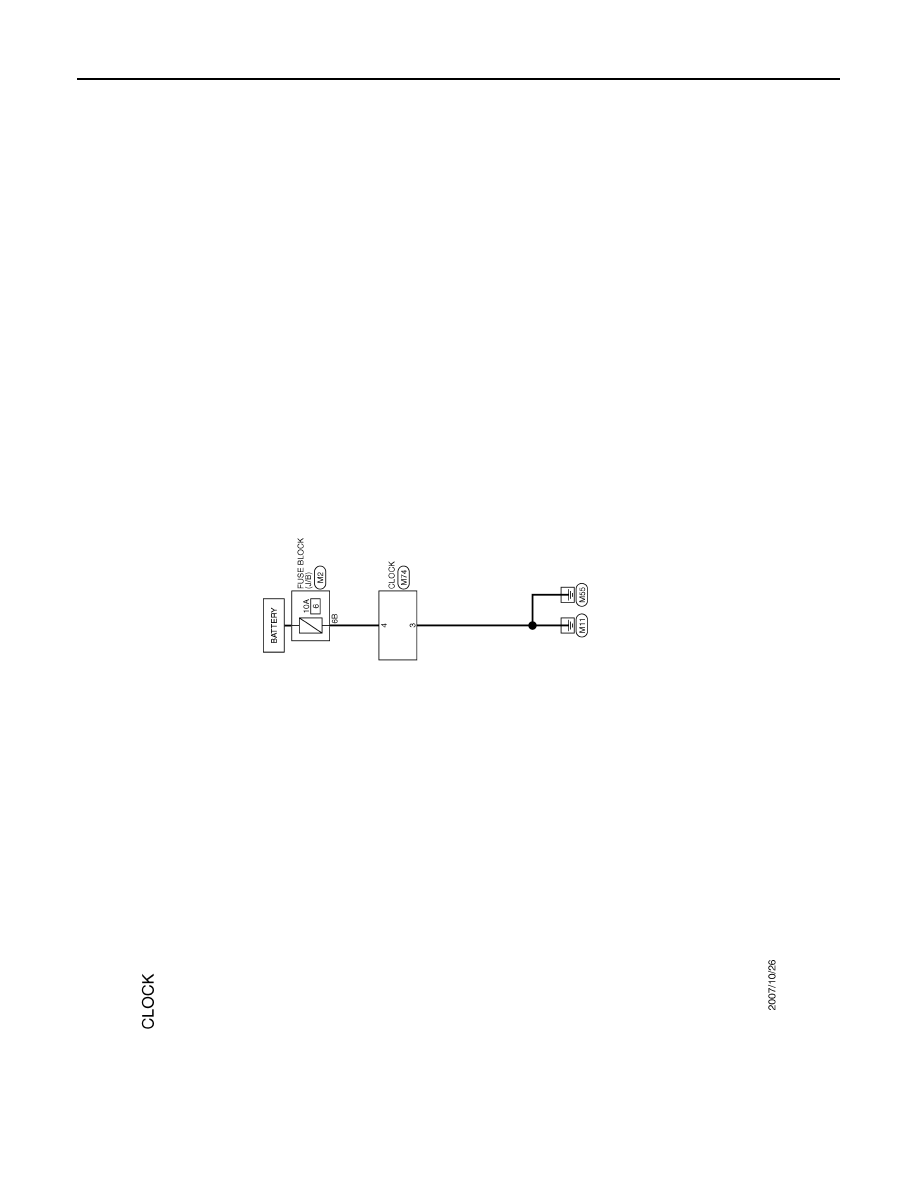
CLOCK
Wiring Diagram - CLOCK -
INFOID:0000000003140228
JCNWM0719GB
|
|
|
Content .. 1096 1097 1098 1099 ..
MWI-70 < COMPONENT DIAGNOSIS > CLOCK CLOCK Wiring Diagram - CLOCK - INFOID:0000000003140228 JCNWM0719GB |