Infiniti EX35. Manual - part 1086


  Index      Infiniti     Infiniti EX35 - service repair manual 2008 year


Search            


Content   ..  1084  1085  1086  1087   ..


Infiniti EX35. Manual - part 1086


MWI-22

< FUNCTION DIAGNOSIS >

METER SYSTEM

ODO/TRIP METER : Component Description

INFOID:0000000003140160

SHIFT POSITION INDICATOR

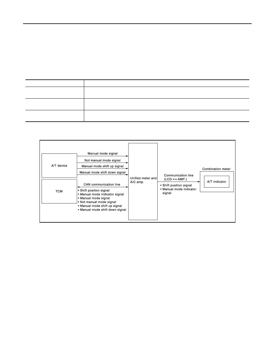
SHIFT POSITION INDICATOR : System Diagram

INFOID:0000000003140161

SHIFT POSITION INDICATOR : System Description

INFOID:0000000003140162

Shift position is displayed in the information display LCD in the combination meter.

MANUAL MODE

• Unified meter and A/C amp. inputs manual mode signal and shift-up/down signal from A/T device (manual

mode switch), and transmits the signals to TCM with CAN communication line.

• TCM processes manual mode signal and shift-up/down signal, and transmits manual mode indicator signal

and shift position signal to unified meter and A/C amp. with CAN communication line.

• Unified meter and A/C amp. transmits manual mode indicator signal and shift position signal to combination

meter with the communication line.

• Combination meter indicates A/T gear position and manual mode indicator, when receiving manual mode

indicator signal and shift position signal.

NOT MANUAL MODE

• Unified meter and A/C amp. inputs not manual mode signal from A/T device (manual mode switch), and

transmits the signals to TCM with CAN communication line.

• TCM transmits shift position signal to unified meter and A/C amp. with CAN communication line.
• Unified meter and A/C amp. transmits shift position signal to combination meter with the communication line.
• Combination meter indicates A/T shift position when receiving shift position signal.

7.

ABS actuator and electric unit (con-
trol unit)

8.

Unified meter and A/C amp.

9.

Combination meter

10. Fuel level sensor unit (sub)

A.

Rear seat (inside right)

B.

Dash side finisher (passenger side)

C.

Hoodledge cover (RH)

D.

2WD [oil pan (upper) RH side]

E.

AWD (oil filter bracket part)

F.

Condenser (front)

G.

Hoodledge cover (LH)

H.

Behind cluster lid C

I.

Rear seat (inside left)

Unit

Description

Combination meter

The combination meter calculates the vehicle distance according to the vehicle speed signal. The 
vehicle distance is displayed.

Unified meter and A/C amp.

The unified meter and A/C amp. transmits the vehicle speed signal from ABS actuator and electric 
unit (control unit) to the combination meter.

ABS actuator and electric unit 
(control unit)

Transmits the vehicle speed signal to the unified meter and A/C amp. with CAN communication 
line.

JPNIA0758GB

MWI

METER SYSTEM

MWI-23

< FUNCTION DIAGNOSIS >

C

D

E

F

G

H

I

J

K

L

M

B

A

O

P

SHIFT POSITION INDICATOR : Component Parts Location

INFOID:0000000003733001

1.

Fuel level sensor unit and fuel pump 
(main)

2.

BCM

3.

IPDM E/R

4.

ECM : 

EC-22, "Component Parts Lo-

cation"

5.

Oil pressure switch

6.

Ambient sensor

JPNIA0868ZZ

MWI-24

< FUNCTION DIAGNOSIS >

METER SYSTEM

SHIFT POSITION INDICATOR : Component Description

INFOID:0000000003140164

WARNING LAMPS/INDICATOR LAMPS

WARNING LAMPS/INDICATOR LAMPS : System Diagram

INFOID:0000000003140165

WARNING LAMPS/INDICATOR LAMPS : System Description

INFOID:0000000003140166

OIL PRESSURE WARNING LAMP

• IPDM E/R inputs oil pressure switch signal from oil pressure switch, and transmits the signal to unified meter

and A/C amp. through BCM with CAN communication line.

• Unified meter and A/C amp. transmits oil pressure switch signal to combination meter with communication

line.

• Let the combination meter turn oil pressure warning lamp ON with received oil pressure switch signal.

7.

ABS actuator and electric unit (con-
trol unit)

8.

Unified meter and A/C amp.

9.

Combination meter

10. Fuel level sensor unit (sub)

A.

Rear seat (inside right)

B.

Dash side finisher (passenger side)

C.

Hoodledge cover (RH)

D.

2WD [oil pan (upper) RH side]

E.

AWD (oil filter bracket part)

F.

Condenser (front)

G.

Hoodledge cover (LH)

H.

Behind cluster lid C

I.

Rear seat (inside left)

Unit

Description

Combination meter

Displays the shift position on the information display with shift position signal and manual mode in-
dicator signal received from unified meter and A/C amp.

Unified meter and A/C amp.

• Transmits the signals from the A/T device to TCM with CAN communication line.
• Transmits shift position signal and manual mode indicator signal received from TCM with CAN 

communication line to the combination meter by means of communication line.

A/T device

Transmits the following signals to the unified meter and A/C amp.

• Manual mode signal

• Not manual mode signal

• Manual mode shift up signal

• Manual mode shift down signal

TCM

Transmits shift position signal and manual mode indicator signal to the unified meter and A/C amp.

JPNIA0969GB

MWI

METER SYSTEM

MWI-25

< FUNCTION DIAGNOSIS >

C

D

E

F

G

H

I

J

K

L

M

B

A

O

P

WARNING LAMPS/INDICATOR LAMPS : Component Parts Location

INFOID:0000000003733003

1.

Fuel level sensor unit and fuel pump 
(main)

2.

BCM

3.

IPDM E/R

4.

ECM : 

EC-22, "Component Parts Lo-

cation"

5.

Oil pressure switch

6.

Ambient sensor

JPNIA0868ZZ


Content   ..  1084  1085  1086  1087   ..