Content .. 1077 1078 1079 1080 ..
Infiniti EX35. Manual - part 1079
INSIDE MIRROR
MIR-71
< ON-VEHICLE REPAIR >
[WITHOUT ADP]
C
D
E
F
G
H
I
J
K
M
A
B
MIR
N
O
P
ON-VEHICLE REPAIR
INSIDE MIRROR
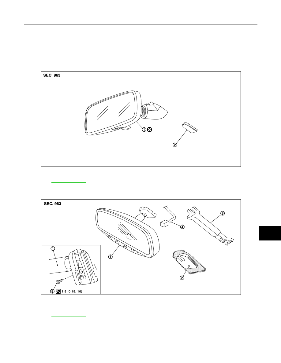
Exploded View
INFOID:0000000003777987
Base
Option
Removal and Installation
INFOID:0000000003777988
REMOVAL
Base model
1.
Inside mirror
2.
Mirror base
for symbols in the figure.
JMLIA0145ZZ
1.
Inside mirror
2.
Mirror base
3.
Inside mirror cover
4.
Harness connector
5.
TORX bolt
for symbols in the figure.
JMLIA0146GB