Infiniti EX35. Manual - part 100
AV
AUDIO SYSTEM
AV-181
< FUNCTION DIAGNOSIS >
[BOSE AUDIO WITHOUT NAVIGATION]
C
D
E
F
G
H
I
J
K
L
M
B
A
O
P
AUDIO SYSTEM
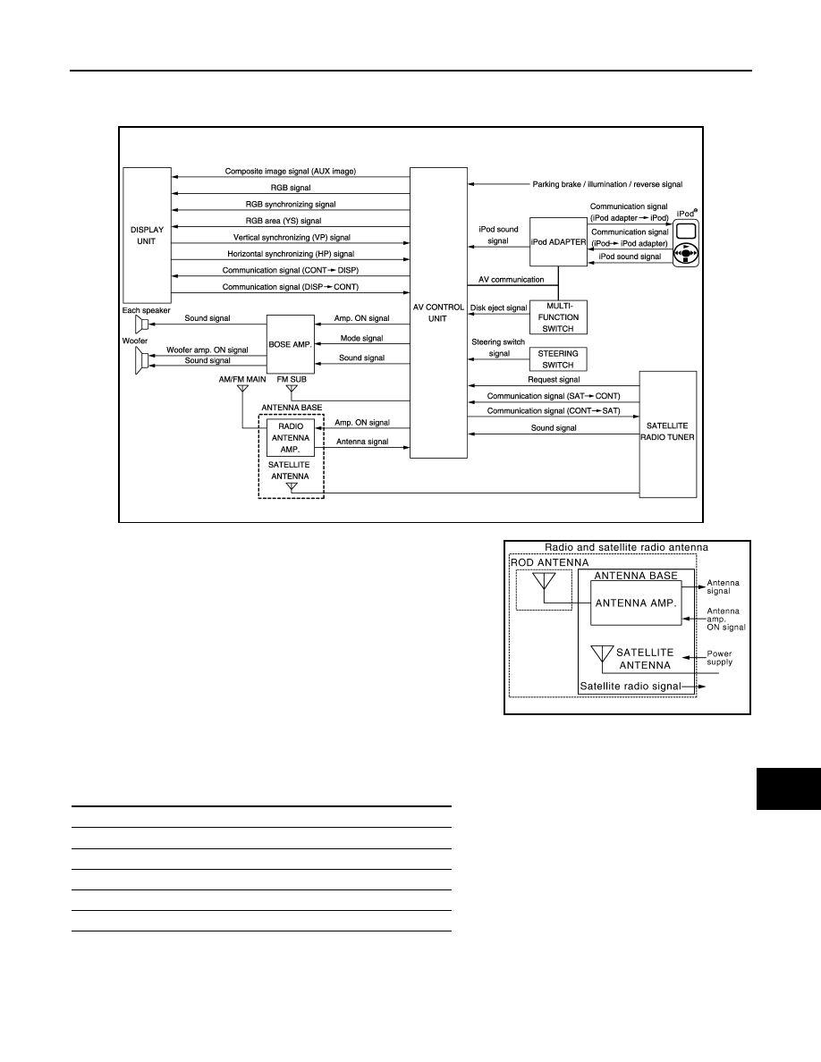
System Diagram
INFOID:0000000003508654
NOTE:
A radio antenna base integrated with radio antenna and satellite
radio antenna is adopted.
System Description
INFOID:0000000003508655
The audio system is equipped with the following functions. Each function can be operated by multifunction
switch, preset switch or steering switch. It indicates the operation status of AUDIO to display.
FUNCTION DESCRIPTION
Operating signal
Operation of the audio system can be performed with multifunction switch, preset switch or steering switch.
JSNIA0699GB
JSNIA1062GB
Function
AM/FM radio
Satellite radio
CD
iPod connection
Driver's Audio Stage