Hyundai Santa Fe (2006 year). Manual - part 487
FLA -14
FUEL SYSTEM
SENSOR
ECM
(A)
(B)
(C)
1
1
1
1
2
2
2
2
FIG 2
BFGE501B
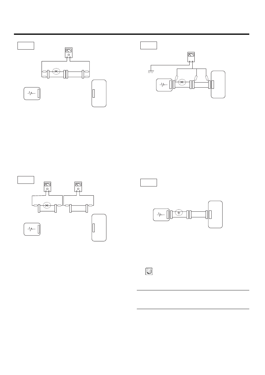
b.
Disconnect connector (B), and measure for resis-
tance between connector (C) and (B1) and be-
tween (B2) and (A) as shown in [FIG. 3].
In this case the measured resistance between
connector (C) and (B1) is higher than 1㏁ and the
open circuit is between terminal 1 of connector
(C) and terminal 1 of connector (B1).
SENSOR
ECM
(A)
(B2)
(C)
1
1
1
1
2
2
2
2
FIG 3
(B1)
BFGE501C
3.
Voltage Check Method
a.
With each connector still connected, measure the
voltage between the chassis ground and terminal
1 of each connectors (A), (B) and (C) as shown
in [FIG. 4].
The measured voltage of each connector is 5V,
5V and 0V respectively. So the open circuit is
between connector (C) and (B).
V
SENSOR
ECM
(A)
(B)
(C)
1
1
1
1
2
2
2
2
FIG 4
BFGE501D
● CHECK SHORT CIRCUIT
1.
Test Method for Short to Ground Circuit
• Continuity Check with Chassis Ground
If short to ground circuit occurs as shown in [FIG. 5],
the broken point can be found by performing Step 2
(Continuity Check Method with Chassis Ground) as
shown below.
SENSOR
ECM
(A)
(B)
(C)
1
1
1
1
2
2
2
2
FIG 5
BFGE501E
2.
Continuity Check Method (with Chassis Ground)
NOTE
Lightly shake the wire harness above and below, or
from side to side when measuring the resistance.
Specification (Resistance)
1Ω or less → Short to Ground Circuit
1MΩ or Higher → Normal Circuit