Hyundai Santa Fe (2006 year). Manual - part 403


  Index      Hyundai     Hyundai Santa Fe - service repair manual 2006 year


Search            


Content   ..  401  402  403  404   ..


Hyundai Santa Fe (2006 year). Manual - part 403


FL -222

FUEL SYSTEM

DTC P0237 BOOST PRESSURE SENSOR CIRCUIT LOW INPUT

COMPONENT LOCATION

EDAB9384

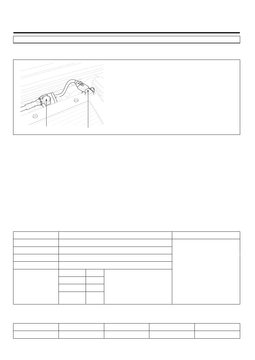
VGT Control Solenoid Valve

BPS & IATS #2

SCMFL6500L

GENERAL DESCRIPTION

EAB17743

Boost Pressure Sensor(BPS) is installed in intake manifold and senses the pressure of air inside of intake manifold which
is compressed by turbo charager.Measuring mass air flow accurately with the information of intake mainfold pressure,
mass air flow and intake air temperature, ECM performs actuating correction of EGR and VGT.When excessive intake
manifold pressure is detected, engine power generation is limited to protect engine because too highly compressed pres-
sure due to turbo charger may harm engine.

DTC DESCRIPTION

ECCB5E26

P0237 is set when the voltage below 0.2V - mimimum output voltage of BPS - is detected for more than 2 sec.. This code
is due to open in power circuit or short to ground in signal circuit.

DTC DETECTING CONDITION

EAF655CC

Item

Detecting Condition

Possible Cause

DTC Strategy

• Voltage monitoring

Enable Conditions

• IG KEY "ON"

Threshold Value

• Output signal below minimum value(below 200mV)

Diagnostic Time

• 2 sec.

Fuel cut

NO

EGR Off

YES

Fuel Limit

YES

Fail Safe

Check

Lamp

YES

• Boost pressure is fixed

at 1000 hpa.

• BPS circuit
• BPS component

SPECIFICATION

E86C9D22

Pressure [Kpa]

20

100

190

250

Output voltage [V]

0.4±0.077

1.878±0.063

3.541±0.063

4.650±0.077

DTC TROUBLESHOOTING PROCEDURES

FL -223

SCHEMATIC DIAGRAM

E069DAF8

BPS & IATS #2

C283

1

2

ECM C230-A (13)

BPS Signal

Reference Voltage (+5V)

ECM C230-A (40)

3

4

ECM C230-A (23)

IATS #2 Signal

Sensor ground

ECM C230-A (53)

ECM (C230-A)

BPS & IATS #2 (C283)

 P

1

2

4

23 - GND

53 - IATS #2 Signal

13 - Reference Voltage (+5V)

40 - BPS Signal

[CIRCUIT DIAGRAM]

[HARNESS CONNECTORS]

[CONNECTION INFORMATION]

Terminal

Connected to

Function

ECM

C230-A

C230-K

1

2

4

3

6

5

8 7

12

13

16

17

18

23 22

20

21

19

27 26 25 24

28

29

30

14

9

10

11

15

33 32 31

34

37

41

42

40 39 38

35

36

43

44

47 46

49 48

50

53

56

58 57

54

51

52

55

59

60
45

1

30 29

31

32

38

39

36

37

35

33

34

40

42 41

46 45 44 43

48 47

50 49

2

3

4

6

5

8

7

12 11 10 9

13

14

15

18 17

19

16

22

25

27 26

23

20

21

24

28

51

75 74
53 52

73

79 78 77 76

80

81

83 82

84

86 85

87

89 88

90

92 91

93

94

57

69 68

70

71

64

54

55

56

61

58

59

60

63 62

65

66

67

72

4

3

2

1

SCMFL6118L

SIGNAL WAVEFORM AND DATA

EF4BFE1E

Fig.1

Fig1). This is the waveform of BPS as accelerating from idle state. Signal voltage rises as accelerating.

              BPS signal

LFIG208A

MONITOR SCANTOOL DATA

EBE79CFF

1.

Connect Scantool to Data Link Connector (DLC).

FL -224

FUEL SYSTEM

2.

Warm engine up to normal operating temperature.

3.

Turn "OFF" electrical devices and A/C.

4.

Monitor "BOOST PRESSURE SENSOR" parameter on the Scantool.

Specification : 1000hpa ± 100hpa(VGT actuator : approx. 76%) at idle

Fig.1

Fig.2

Fig1) Monitor "BOOST PRESSURE SENSOR" parameter on the Scantool at idle after warming engine up.
         1000hpa 100hpa(approx. 1 atm) is correct value.
Fig.2) VGT actuator duty and boost pressure at acceleration is shown . If boost pressure rises and reaches certain value, 
          VGT actuator duty stops to drop and keeps steady. Releasing accelerator pedal at this moment, VGT actuator duty 
          drops to approx. 45%, then if RPM drops to idle range, duty returns to 76%. 

SCMFL6253L

TERMINAL AND CONNECTOR INSPECTION

EE30EC4D

1.

Electrical systems consist of a lot of harness and connectors, poor connection of terminals can cause various prob-
lems and damge of component.

2.

Perform checking procedure as follows.

1)

Check damage of harness and terminals : Check terminals for contact resistance, corrosion and deformation.

2)

Check connecting condition of ECM and component connector : Check terminal seperation, damage of locking
device and connecting condition between terminal and wiring.

NOTE

Disconnect the pin which requires checking at male connector and insert it to the terminal at female connector for
checking connecting condition. ( after checking, reconnect the pin at correct position. )

3.

Is the problem found?

YES

Repair the trouble causing part and go to "Verification of Vehicle Repair".

NO

Go to "Power Circuit Inspection".

DTC TROUBLESHOOTING PROCEDURES

FL -225

POWER CIRCUIT INSPECTION

E863B4E7

1.

IG KEY "OFF", ENGINE "OFF".

2.

Disconnect BPS connector.

3.

IG KEY "ON".

4.

Measure the voltage of BPS connector terminal 2.

Specification : 4.8V~5.1V

5.

Is the measured voltage within the specification?

YES

Go to "Signal Circuit Inspection".

NO

Repair open in power circuit and go to "Verification of Vehicle Repair".

SIGNAL CIRCUIT INSPECTION

EEE0DDF7

1.

Check signal circuit voltage

1)

IG KEY "OFF", ENGINE "OFF".

2)

Disconnect BPS connector.

3)

IG KEY "ON"

4)

Measure the voltage of BPS connector terminal 1.

Specification : 4.8V~5.1V

5)

Is the measured voltage within the specification?

YES

Go to "Component Inspection".

NO

Go to "2. Check short to ground in signal circuit" as follows.

2.

Check short to ground in signal circuit

1)

IG KEY "OFF", ENGINE "OFF"

2)

Disconnect BPS connector and ECM connector.

3)

Check continuity between BPS connector terminal 1 and chassis ground.

Specification : Discontinuity (Infinite

)

4)

Is the measured resistance within the specification?


Content   ..  401  402  403  404   ..