Hyundai Tiburon (2003 year). Manual - part 158


  Index      Hyundai     Hyundai Tiburon - service repair manual 2003 year


Search            


Content   ..  156  157  158  159   ..


Hyundai Tiburon (2003 year). Manual - part 158


38 ~ 39 

Shorting bar 

40 

Not used 

41 ~ 42 

Shorting bar 

43 ~ 44 

Shorting bar 

45 

Driver satellite sensor, Low 

Input 

46 

Passenger satellite sensor, Low 

Input 

47 

Not used 

48 

Not used 

49 

Not used 

50 

Not used 

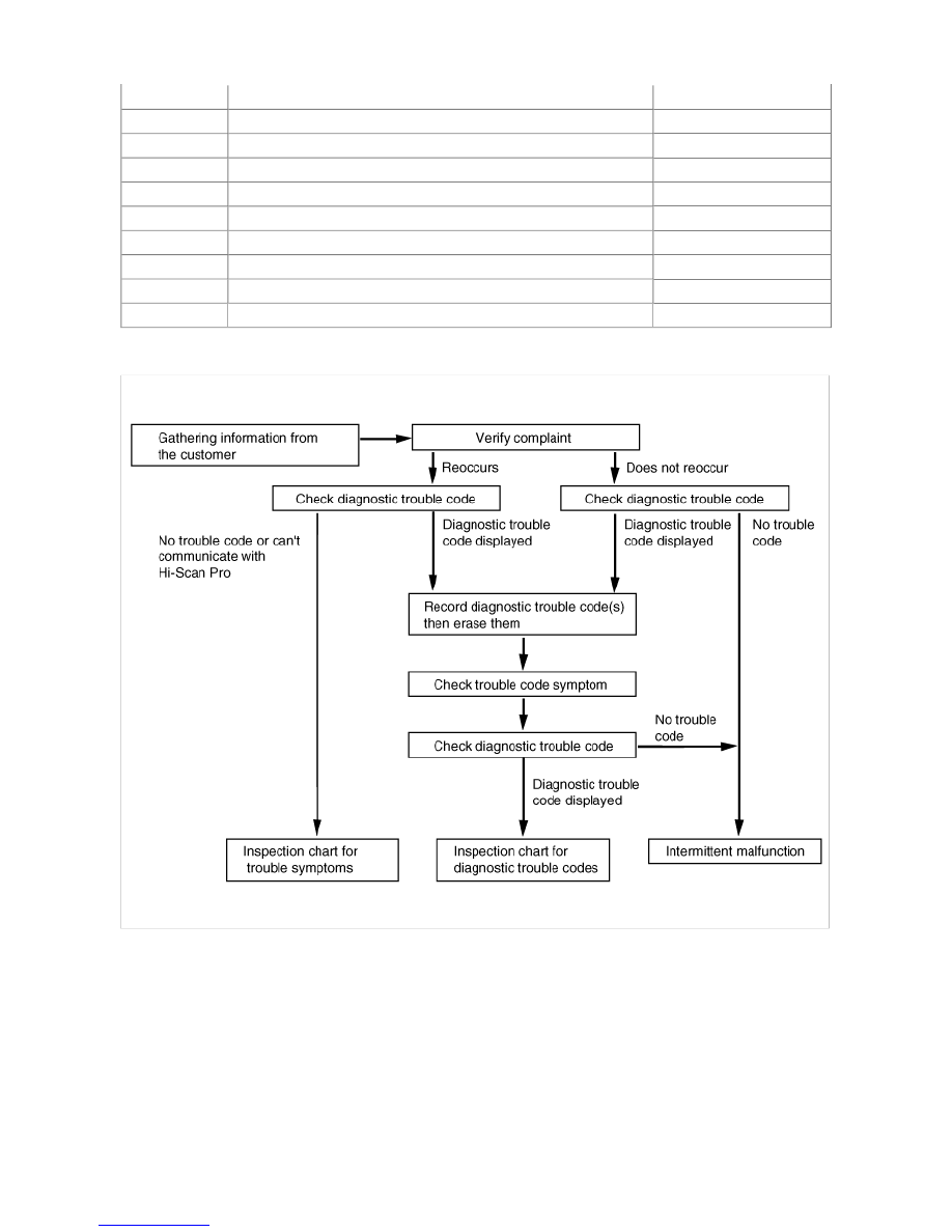
DIAGNOSTIC TROUBLESHOOTING FLOW


The clock spring (coil spring) consists of two current carrying coils. It is attached between the steering column and the 
steering wheel. It allows rotation of the steering wheel while maintaining continuous contact of the deployment loop through 
the inflator module. 


The SRSCM is supported with the side airbag function by two satellites, which act as intelligent acceleration sensors and 
as such back up the central airbag controller. Both the satellites continuously report the system statuson the left and right-
hand sides of the vehicle to the SRSCM. 


TIBURON(GK) > 2003 > G 2.7 V6 DOHC > Restraint > Supplemental Restraint System Control Module (SRnodeM) 
> Description and Operation, TIBURON(GK) > 2003 > G 2.7 V6 DOHC > Restraint > Supplemental Restraint 
System Control Module (SRnodeM) > Description and Operation

SRS HARNESS

SRSCM INDEPENDENT LAMP ACTIVATION

1. Loss of ignition voltage supply to the SRSCM : lamp turned on continuously. 

2. Loss of internal operating voltage : lamp turned on continuously. 

3. SRSCM not connected : lamp turned on through shorting bar in wiring harness connector. 


MIL OPERATING METHOD

CLOCK SPRING

SATELLITE SENSOR

When the ignition is ON, never cause a sudden shock around the installation area of the satellite sensor by a hammer, 

The SRS airbag system has sophisticated electrical and electronic components. Therefore the airbag operating 
components should be handled very carefully. 
The SRSCM will deploy the airbag modules by sensing the frontal impact sensed by the sensor built in to the SRSCM. 


etc. Otherwise it could cause the airbag system to unexpectedly deploy during servicing. 

SRSCM

1. DC/DC convertor : The DC/DC converter in the power supply includes a step-up and a step-down converter, which 

provides the firing voltage for four firing circuits and the internal operating voltage. If the internal operating voltage falls 
below a defined threshold, a reset is executed. 

2. Arming sensor/safing sensor : The arming/safing sensor built in to the airbag firing circuit has the function of arming the 

airbag circuit under all required deployment conditions and maintaining the airbag firing circuits unarmed under normal 
driving conditions. The safing sensor is a dual-contact electro mechanical switch that closes if it experiences a 
deceleration exceeding a specified threshold. 

3. Back-up power : The SRSCM reserves an energy reserve to provide deployment energy for a short period when the 

vehicle voltage is low or if lost in a vehicle frontal crash. 

4. Back-up power : The SRSCM reserves an energy reserve to provide deployment energy for a short period when the 

vehicle voltage is low or if lost in a vehicle frontal crash. 

5. Malfunction detection : The SRSCM continuously monitors SRS operating status while the ignition key is turned on and 

detects possible malfunctions in the system. The malfunction can be displayed in the form of a diagnostic trouble code 
using the Hi-Scan Pro. 

6. MIL (Malfunction Indication Lamp) notification : If any fault is detected, the SRSCM sends a signal to the indicator lamp 

on the instrument cluster to warn the vehicle driver. 
The MIL indicator is the key item in notifying the driver of SRS faults. It verifies lamp and SRSCM operation by flashing 
6 times when the ignition switch is first turned on. 

7. Malfunction recording : Once a fault occurs in the system, the SRSCM records the fault in memory in the form of a 

DTC, which can only be erased by the Hi-Scan Pro. 

8. Data link connector : SRSCM memory stored is linked through this connector located under neath the driver side crash 

pad to an external output device such as the Hi-Scan Pro. 

9. What if only BPT's deploy. 

10. Crash output 

The crash output is used to unlock the doors in case of a crash. The crash output is : 0 ~ 200 

µ

A in OFF mode and 

200mA in ON mode. During the unlock command, the switch is closed for 200 mS. 

DIAGNOSIS WITH SCAN TOOL

CHECK PROCEDURES

1. Connect the Hi-Scan Pro DLC to the vehicle's data link connector located underneath the dash panel. 

2. Turn the ignition key to the "ON" position and turn the Hi-Scan Pro ON. 

3. Perform the SRS diagnosis according to the vehicle model configuration. 

4. If a fault code is assured, then replace the component. Never attempt to repair the component. 

5. If the Hi-Scan Pro finds that a component of the system is faulty, there is a possibility that the fault is not in the 

component, but in SRS wiringor connector. 

SPECIFICATION


DAB 


PAB, SAB, BPT 

AIRBAG SQUIB RESISTANCE LIMITS

 1.06


Resistance too low 

Fault definitely detected 

1.80


 R 

 3.40


Resistance whithin tolerance 

Definitely no fault detected 

 6.70


Resistance too high 

Fault definitely detected 

1.06

 < R < 1.80


3.40

 < R < 6.70


Tolerance band 

Fault may or may not be detected 

 0.4


Resistance too low 

Fault definitely detected 

1.6


 R 

 2.8


Resistance whithin tolerance 

Definitely no fault detected 

 5.4


Resistance too high 

Fault definitely detected 

0.4

 < R < 1.6


Tolerance band 

Fault may or may not be detected 


Content   ..  156  157  158  159   ..