Hummer H1 (2006+). Manual - part 348


  Index      Hummer     Hummer H1 DMAX - service repair manual 2006 year


Search            


Content   ..  346  347  348  349   ..


Hummer H1 (2006+). Manual - part 348


12-68

Electrical System

_______________________________________________________

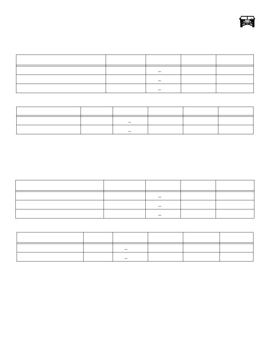
readings should approximate the specifications. The coolant temperature warning light and gauge reference the same dark green
wire (CKT 39). If the light is activating at a questionable point, reference the chart to verify accuracy  (Figure 12-110).

Fuel Gauge and Warning Light Calibration.

To check accuracy of the fuel gauge or warning light use the calibration chart. The gauge panel must be connected to the harness to verify
the fuel level. Back probe the signal wire with a DVOM, and check the resistance verses the gauge readings. The readings should approx-
imate the specifications. The fuel level warning light and gauge reference the same pink wire (CKT 29). If the light is activating at a ques-
tionable point, reference the chart to verify accuracy.

Warning Lights for the Coolant/Fuel Module

All the LEDs on the coolant/fuel module receive voltage from a control circuit that is built in to the module. This controller is powered up
with system voltage on the tan wire (CKT 916)  (Figure 12-112).

The warning and indicator lights are also connected to a 4.1 second timed bulb check circuit. This is activated by a voltage signal being
supplied to the module through the grey wire with a black tracer (CKT 911). When the module receives the voltage signal it activates an
internal timer which supplies a ground to all the LEDs on the board.

ABS Warning Light

The ABS warning Light is an amber LED. It is controlled by a ground signal supplied by the ABS ECU on the red wire (CKT 603).

Brake Warning Light

The brake warning light is a red LED. It is controlled by a ground signal supplied by either the parking brake switch or the low brake fluid
switch. The signal is supplied on the brown wire (CKT 42).

 Coolant Temperature Gauge Calibration Check

Approximate Reading

Input

Input Tol.

Ascending

Descending

Cold

1500 

1

+ 5 

1

X

Mid. Point

260 

1

+ 5 

1

X

Hot

56 

1

+ 3 

1

X

 Coolant Temperature Light Calibration Check

Approximate Reading

Inputs

Input Tol.

Ascending

Descending

Status

Red Band

75 

1

+5

X

On

Gray Band

>80 

1

+5

X

Off

 Fuel Gauge Calibration Checks

Approximate Readings 

Inputs

Input Tol

Ascending

Descending

Empty

272 

1

+5

1

X

1/2

113 

1

+5

1

X

Full

20  

1

+3

1

X

 Low Fuel Warning Light

Approximate Readings 

Inputs

Input Tol

Ascending

Descending

Status

1/8

210 

1

+10

1

X

ON

1/4

145 

1

+10

1

X

OFF

______________________________________________________

 Electrical System  12-69

Low Coolant Warning Light.

The low coolant warning light is an amber LED. It is controlled by a ground signal supplied by the low coolant switch on the red wire (CKT
794).

TT4 Indicator Light

The TT4 indicator light is an amber LED. It is controlled by a ground signal supplied by the ABS ECU on the purple wire (CKT 961).

Coolant Temperature Warning Light

The coolant temperature warning light is a red LED. It is controlled by an internal driver in the gauge module circuit board. This driver
watches the coolant temperature signal that is supplied on the dark green wire (CKT 39). When the driver sees resistance on the dark
green wire (CKT 39) fall to < 75 

1 it activates the LED. It will not turn the LED off until it sees resistance > 80 1.

Low Fuel Warning Light

The low fuel warning light is an amber LED. It is controlled by an internal driver in the gauge module. This driver watches the signal on the
pink wire (CKT 29). When resistance on the pink wire (CKT 29) increases to 210 

1 the driver will activate the LED. The LED will remain

on until the driver sees that the resistance on the signal has fallen below 145 

1.

NOTE: The fuel gauge is heavily dampened to prevent erratic readings. As a result fuel light activation may occur before the
gauge reads low.

ELocker Warning Light

The Elector warning light is an amber LED. It is controlled by a ground signal supplied by the ELocker control module on the
white wire with a black tracer (CKT 879).

Warning/Indicator “Bulb Check”

When the ignition is turned to the “Run” position the “Bulb Check” should operate. The “Bulb Check” is a 4.1 second      (+ 1.0)
test to see that all indicator and warning lights are functioning. If the “Bulb Check” fails to operate correctly, refer to the diagnostic
chart.

12-70

Electrical System

_______________________________________________________

AUXILLARY COOLANT PUMP

The auxiliary coolant pump is located at the right front of the engine compartment. One hose attaches to the EGR cooler and the
other to the transfer case by-pass valve. It has two purposes:

• To give a little extra boost to the flow of coolant through the EGR cooler at low water pump speeds. 

• To provide protection against heat soaking of the engine. 

The auxiliary coolant pump will stay on after engine shut down to circulate coolant and reduce hot spots. A temperature switch lo-
cated on the top of the radiator will close and then open when the coolant temperatures is back to acceptable level.

Figure 12-53:   Cooling Plumbing W/ T-case Valve and Auxiliary Coolant Pump

AUXILIARY

COOLANT PUMP

______________________________________________________

 Electrical System  12-71

AUXILIARY COOLANT PUMP SWITCH

The operation of the pump once the key is off is via the temperature switch in the top of the radiator. The switch circuit closes when
the coolant temperature exceeds 215°F (+/-5°F) and turns on the pump. There is a little hysteresis designed in so the pump switches
off at a slightly lower temperature as the coolant temperature decreases.

CTIS GAUGE AND CONTROL MODULE 

The CTIS module is located on the right side of the coolant/fuel module. It contains a tire pressure gauge, a low air pressure warn-
ing light, a CTIS air compressor indicator, a tire selector switch and an inflate/deflate switch (Figure 12-54).

The air pressure gauge has a domed lens to reduce glare. The low air pressure warning light and the CTIS air compressor indicator
light are LEDs to improve visibility.

Serviceable items on the CTIS module include the air pressure gauge, the selector switch, the inflate/deflate switch and all the back
lighting bulbs. The LED warning and indicator lights are not serviceable.

Figure 12-54:   CTIS Module

CTIS Module Replacement

WARNING:  The CTIS system components are subject to high air pressure. Always relieve the air pressure prior to
servicing the CTIS system. Failure to follow this warning may result in serious injury.

Removal

1.

Relieve the CTIS system air pressure (Refer to section 6).

2.

Remove the four allen screws from the bezel around the CTIS/RADIO/. 


Content   ..  346  347  348  349   ..