Hummer H1 (2006+). Manual - part 341
12-40
Electrical System
_______________________________________________________
12.
Turn the ignition ON leaving the engine OFF.
Reconnect the glow plug relay control harness.
With a DMM connected to ground, back probe
the glow plug relay signal circuit (506 LB) at the
ECM harness connector. Use a scan tool to com-
mand the glow plugs ON. Observe the DMM
while the glow plugs are commanded ON.
Is the voltage at the specified value?
5.0-5.6 Volts
Go to step 21.
Go to step 13.
13.
Turn the ignition OFF. Disconnect the right and
left bank glow plug output circuit connectors at
the glow plug relay. With an unpowered test lamp
connected to B+, probe each circuit.
Does each circuit turn ON the test lamp?
Go to step 26.
Go to step 14.
14.
Turn the ignition OFF. Disconnect each glow plug
connector at the glow plug that did not illuminate
the test lamp. With an unpowered test lamp con-
nected to B+, probe the terminal on the glow
plug.
Does each glow plug illuminate the test lamp?
Go to step 26.
Go to step 25.
15.
Turn the ignition OFF. Disconnect each glow plug
connector at the glow plug. With an unpowered
test lamp connected to B+, probe each circuit at
the glow plug output connectors.
Is the test lamp OFF at each of the circuits?
Go to step 20.
Go to step 27.
16.
Repair an open or a short to ground in the glow
plug relay ignition feed circuit (CKT 239 RD).
Did you complete the repair?
Go to step 30.
17.
Repair any opens or poor connections in the glow
plug relay ground circuit (BK).
Did you complete the repair?
Go to step 30.
18.
Inspect the glow plug relay control circuit (466
YL) for an open or short to ground. If the glow
plug relay control circuit is open or shorted to
ground, repair as necessary.
Did you find and correct the condition?
Go to step 30.
Go to step 19.
19.
Inspect the glow plug relay control circuit (CKT
466 YL) for a proper connection at the ECM and
replace the terminal if necessary.
Did you find an improper connection and make
the necessary repair?
Go to step 30.
Go to step 29.
20.
Inspect the glow plug relay signal circuit (CKT
506 LB) for an open or short to ground. If the
glow plug relay signal circuit is open or shorted
to ground, repair as necessary.
Did you find and correct the condition?
Go to step 30.
Go to step 28.
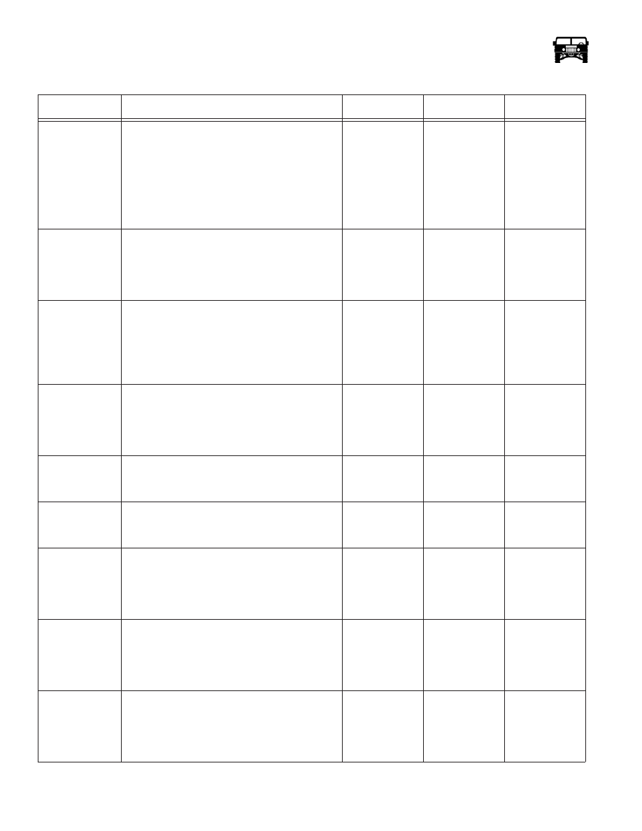
Glow Plugs Inoperative (Cont’d) (Figure 12-117)
Step
Action
Value
Yes
No