Hummer H1 (2006+). Manual - part 280


  Index      Hummer     Hummer H1 DMAX - service repair manual 2006 year


Search            


Content   ..  278  279  280  281   ..


Hummer H1 (2006+). Manual - part 280


9-98 Axles, Suspension and Frame

__________________________________________

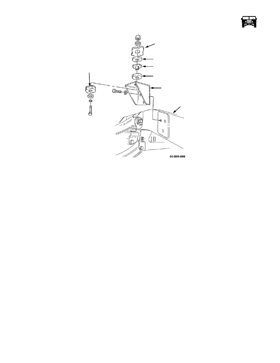
Figure 9-147:   Right Intermediate Body Mount Bracket Replacement

Installation

1.

Apply thread-locking compound to the three bolts and install the body mount bracket on the frame rail with the three washers 
and the bolts. Tighten the bolts to 90 lb-ft. (122 N•m) (Figure  9-147).

2.

Install the right intermediate body mount (Refer to section 10).

Left Intermediate Body Mount Bracket Replacement

Removal

1.

Remove the left intermediate body mount (Refer to section 10).

2.

Remove the tailpipe hanger (Refer to section 11).

3.

Remove the three locknuts, washers and the body mount bracket from the frame rail (Figure  9-148).

Installation

1.

Install the body mount bracket on the three bolts and the frame rail with the three washers and the locknuts. Tighten the lock-
nuts to 90 lb-ft. (122 N•m) (Figure  9-148).

2.

Install the tailpipe hanger (Refer to section 11).

3.

Install the left intermediate body mount (Refer to section 10).

BODY

SPACER

SLEEVE

UPPER

CUSHION

BODY

MOUNT

BRACKET

FRAME

RAIL

LOWER

CUSHION

_________________________________________

 Axles, Suspension and Frame  9-99

Figure 9-148:   Left Intermediate Body Mount Bracket Replacement

Rear-Rear Tie Down Bracket Replacement

Removal

Remove the two locknuts, washers, bolts, washers and the tie-down bracket from the frame rail (Figure  9-149).

Installation

Install the tie down bracket on the frame rail with the two washers, bolts, washers and the locknuts. Tighten the locknuts to 261 lb-
ft. (354 N•m) (Figure  9-149).

Figure 9-149:   Tie Down Bracket Replacement

Rear Upper Control Arm Bracket Replacement

NOTE: The procedure for removing and installing the four rear upper control arm brackets is basically the same. This procedure
covers the right rear upper control arm front bracket.

BODY

SPACER

SLEEVE

UPPER

CUSHION

LOWER

CUSHION

FRAME

RAIL

BODY

MOUNT

BRACKET

TIE DOWN

FRAME RAIL

BRACKET

9-100 Axles, Suspension and Frame

_________________________________________

Removal

1.

Remove the wheel.

2.

Remove the bolt, clamp and the vent line from the bracket, and disconnect the vent line from the fitting  (Figure  9-150).

3.

Remove the two locknuts, washers, bolts, washers and the upper control arm from the two control arm brackets (Figure
 9-151).

4.

Remove the four locknuts, washers, bolts, washers, vent line mounting bracket and the control arm bracket from the frame rail.

Figure 9-150:   Rear Geared Hub Vent Line Location

Installation

1.

Install the control arm bracket and the vent line mounting bracket on the frame rail with the four washers, bolts, washers and
the locknuts. Tighten the locknuts to 172 lb-ft. (233 N•m) (Figure  9-151).

2.

Attach the upper control arm to the two upper control arm brackets with the washers, bolts, washers and the locknuts. Tighten
the locknuts to 260 lb-ft. (353 N•m).

3.

Connect the vent line to the fitting and secure the clamp and the vent line to the bracket with the bolt (Figure  9-150).

4.

Install the wheel.

Figure 9-151:   Rear Upper Control Arm Bracket Replacement

BRACKET

FITTING

GEARED HUB

VENT

LINE

VENT LINE 

FRAME RAIL

CONTROL

UPPER CONTROL ARM

ARM

BRACKET

MOUNTING

BRACKET

________________________________________

 Axles, Suspension and Frame  9-101

Rear-Front Tie down Bracket Replacement

Removal

1.

Remove the wheel (Refer to section 6).

2.

Remove the four locknuts, washers, bolts, washers and the tie down bracket from the frame rail (Figure  9-152).

3.

Remove the two locknuts, washers, bolts, washers, vent tube/speed sensor lead mounting bracket and the tie down bracket
from the rear suspension front crossmember mounting bracket. 

Figure 9-152:   Rear-Front Tie Down Bracket Replacement

Installation

1.

Install the tie down bracket and the vent tube mounting bracket on the rear suspension front crossmember mounting bracket 
with the two washers, bolts, washers and the locknuts. Tighten the locknuts to 90 lb-ft. (122 N•m) (Figure  9-152).

2.

Install the tie down bracket on the frame rail with the four washers, bolts, washers and the locknuts. Tighten the locknuts to
261 lb-ft. (354 N•m).

3.

Install the wheel.

Axle Support/Brake Adapter Bracket Replacement

Removal

NOTE: Only remove one support bracket at a time to maintain rear support of the axle assembly.

1.

Remove the brake caliper and the rotor (Refer to section 7).

2.

Remove the locknut, seal washer and the output flange from the output shaft. Discard the seal washer (Figure  9-153).

3.

Remove the four side bolts and the lower support bolt and remove the axle support/brake adapter from the axle assembly. 

TIE DOWN BRACKET

FRAME RAIL

CROSSMEMBER

MOUNTING

BRACKET

VENT TUBE

SPEED SENSOR LEAD

BRACKET


Content   ..  278  279  280  281   ..