Hummer H1 (2006+). Manual - part 264


  Index      Hummer     Hummer H1 DMAX - service repair manual 2006 year


Search            


Content   ..  262  263  264  265   ..


Hummer H1 (2006+). Manual - part 264


9-34 Axles, Suspension and Frame

__________________________________________

Installation

1.

Position the outer boot and the two clamps on the shaft near the outer joint.

2.

Apply a packet of grease to the outer joint.

3.

Position the outer boot over the outer joint housing and secure the clamp with the boot banding tool J–22610.

4.

Secure the smaller clamp on the boot and shaft with tool J–22610.

5.

Clamp the shaft in a vise with protective jaws.

6.

Position the two clamps on the shaft (Figure  9-60).

7.

Install the inner boot on the shaft. Push the boot past the groove on the shaft.

8.

Install the snap ring and retaining clip into the grooves on the shaft (Figure  9-59).

9.

Align the chamfer splines of the inner bearing assembly with the spline of the shaft. Use a press or a rawhide hammer to install
the inner race until it snaps in place - flush against the spacer ring.

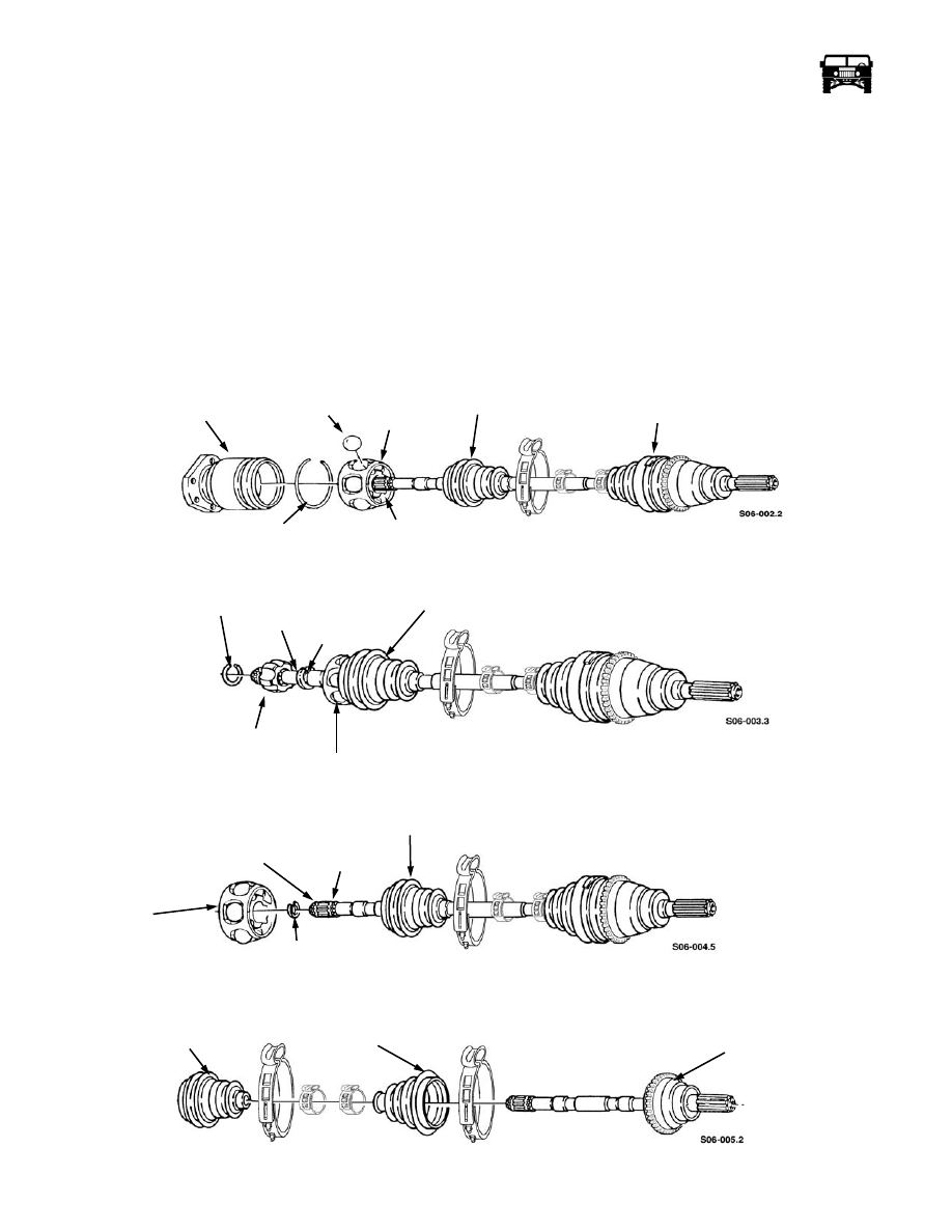
10. Position the six ball bearings into the bearing assembly and retain with a slight amount of grease (Figure  9-57).

Figure 9-57:   Halfshaft Boot Replacement

Figure 9-58:   Halfshaft Boot Replacement

Figure 9-59:   Halfshaft Boot Replacement

Figure 9-60:   Halfshaft Boot Replacement

INNER JOINT HOUSING

RETAINING RING

BEARING

INNER BOOT

OUTER

RACE

INNER RACE

OUTER JOINT

RETAINING CLIP

SHAft

INNER BOOT

OUTER RACE

SNAP RING

INNER RACE

BEARING

SNAP RING

SNAP RING

INNER BOOT

GROOVE

ASSEMBLY

RETAINING

CLIP

GROOVE

INNER BOOT

OUTER BOOT

OUTER

CV JOINT

ASSEMBLY

_________________________________________

 Axles, Suspension and Frame  9-35

11. Position the joint inner housing over the bearing assembly.

NOTE:  Ensure all the ball bearings are in the tracks of the inner joint.

12. Secure the retainer ring in the groove of the inner joint housing.

13. Fill the inner joint with grease from the grease packet.

14. Move the inner boot on the shaft until the boot seats in the groove of the shaft and the inner joint housing.

15. Secure the inner boot on the shaft and the housing with the clamps. Tighten the clamps with the crimping tool J–22610.

16. Slide the halfshaft splines into the geared hub.

17. Apply thread-locking compound to the halfshaft retaining bolt and secure the halfshaft to the geared hub with the lockwasher

and the halfshaft retaining bolt. Tighten the halfshaft retaining bolt to 37 lb-ft. (50 N•m) (Figure  9-56).

18. Install the washer and the access plug into the geared hub. Tighten the access plug to 8-13 lb-ft. (11-18 N•m).

NOTE:  Ensure all six bolt holes in the rotor align with the holes in the output flange. Make sure the mounting holes and bolts are
cleared of old Loctite.

19. Apply Loctite 272 to the six bolts. Secure the halfshaft to the rotor with the twelve lock washers and the bolts. Tighten the

bolts to 48 lb-ft. (65 N•m).

20. Install the wheel.

9-36 Axles, Suspension and Frame

__________________________________________

PROPELLER SHAFT

Front Propeller Shaft

The front propeller shaft is balanced at the factory and only serviced as an assembly.

Front Shaft Removal

CAUTION: Care must be taken to ensure that the front propeller shaft is not seperated at the slip yoke spline. The shaft is bal-
anced at the factory and if seperated it will need to be replaced. 

1.

Remove the four bolts and disconnect the shaft yoke (Figure  9-61).

Figure 9-61:   Front Propeller Shaft Attachment at Axle

2.

Remove the U-joint clamp bolts and the straps and disconnect the front shaft from the transfer case output yoke (Figure  9-62).

FRONT

AXLE

YOKE

FRONT PROPELLER

SHAFT

_________________________________________

 Axles, Suspension and Frame  9-37

Figure 9-62:   Front Propeller Shaft Attachment at Transfer Case

3.

Remove the bolts attaching the center bearing to the engine mount (Figure  9-63).

Figure 9-63:   Center Bearing Attachment

4.

Move the front shaft forward, then rearward over the top of the transfer case and remove from the vehicle.

TRANSFER CASE

OUTPUT YOKE

FRONT PROPELLER

U-BOLT

SHAFT

CENTER BEARING

ENGINE MOUNT


Content   ..  262  263  264  265   ..