Hummer H1 (2006+). Manual - part 240


  Index      Hummer     Hummer H1 DMAX - service repair manual 2006 year


Search            


Content   ..  238  239  240  241   ..


Hummer H1 (2006+). Manual - part 240


7-42

Brake System

_____________________________________________________________

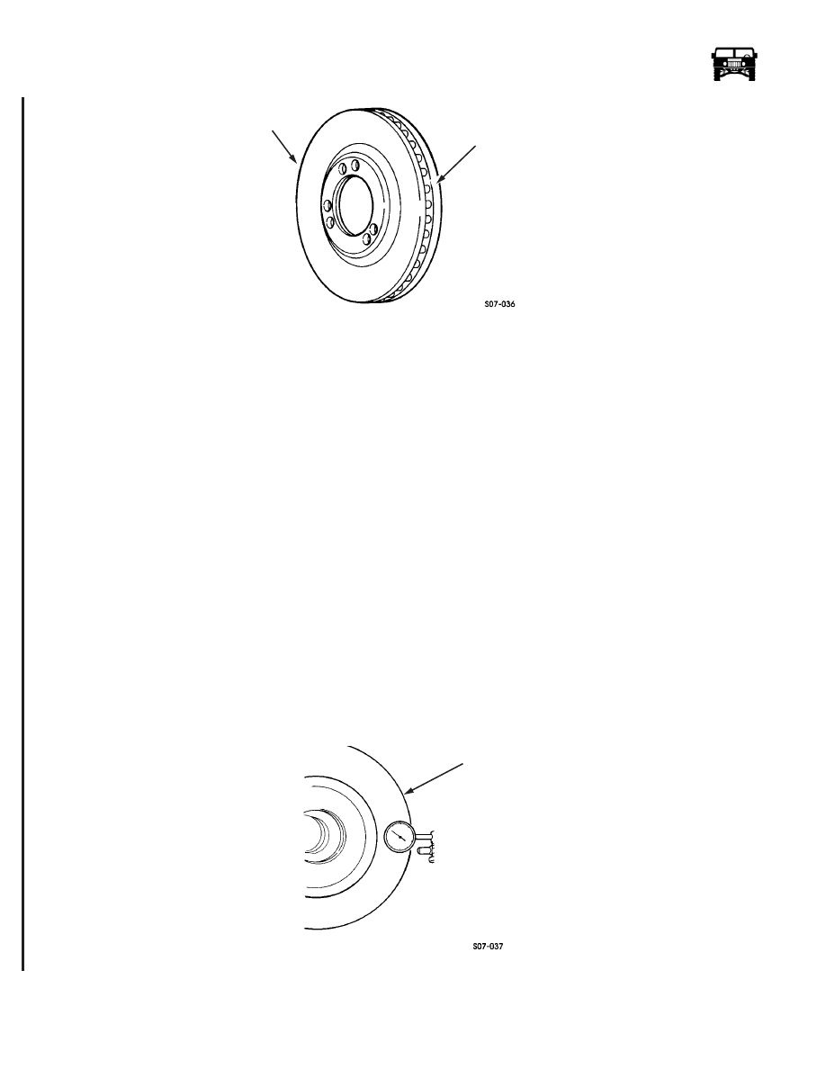
Figure 7-40:   Brake Rotor and Cooling Fins

NOTE: Clean debris from the cooling fins if necessary. 

REFINISHING BRAKE ROTORS

Refinish the rotors only under the following circumstances:

1.

There is a complaint of brake pulsation.

2.

There is excessive scoring. 

Brake rotors have a minimum thickness dimension cast into them. Do not use a brake rotor that will not meet the dimensions
shown in the specifications. Original equipment rotors are surface finished to 0.25-1.27 micrometers (10-50 microinches). 

Accurate control of rotor tolerances is necessary for the proper performance of disc brakes. Machining should be done only with
precision equipment. Service the machining equipment on a regular basis following the manufacturer’s recommended maintenance
procedures.

When you refinish rotors, make sure the attaching adapters, tool holders, vibration dampeners, and tool bits are in good condition.
Always use sharp cutting tools or bits and use only replacement cutting bits recommended by the equipment manufacturer. Dull or
worn tools leave a poor surface finish that will affect initial brake performance. Vibration dampening attachments should always
be used when refinishing braking surfaces. These attachments eliminate tool chatter to allow for a better surface finish. Make sure
these adaptors are clean and free of nicks. The optional swirl pattern finish will provide the best initial braking effectiveness. For
this, use a sanding disc power tool with 120 grit disc for about 10 seconds per side. 

Checking Lateral Runout 

1.

Mount the dial indicator with the stylus contacting the rotor surface 1 in. (25 mm) in from the outer edge (Figure  7-41).

2.

Turn the rotor 360° and note the total indicator reading (TIR).

If lateral runout exceeds 0.004 in. (0.10 mm) TIR, replace or refinish the rotor.

Figure 7-41:   Checking Rotor for Lateral Runout

BRAKE ROTOR

COOLING FINS

ROTOR

6-1-05

____________________________________________________________

 Brake System  7-43

5745804

Checking Thickness Variation

1.

Measure thickness variation of rotor with micrometer at four equally-spaced points around rotor. Measure 1 in. (25 mm) in 
from outer edge (Figure  7-42).

2.

If thickness variation exceeds 0.005 in. (0.13 mm), replace or refinish rotor.

Refinishing

1.

Mount the rotor on the brake lathe and refinish the the surface.

2.

Replace the rotor if refinishing causes the rotor to fall below the minimum thickness of 0.815 in. (20.7 mm).

3.

Install the brake rotor. 

Figure 7-42:   Checking Rotor Thickness

PARKING BRAKE LEVER ADJUSTMENT

Adjustment

1.

Adjust the linkage. 

2.

Put the transmission in PARK, chock the wheels, and release the parking brake handle.

3.

Turn the adjusting knob clockwise as tightly as possible by hand (Figure  7-43).

Figure 7-43:   Parking Brake Lever Location

ROTOR

TRANSMISSION

TRANSFER CASE 

PARKING BRAKE 

LEVER

SHIFT LEVER

HANDLE

SHIFT

ADJUSTING

KNOB

6-1-05

7-44

Brake System

_____________________________________________________________

4.

Apply the parking brake handle.

5.

If the parking brake cannot be applied, turn the adjusting knob counterclockwise until the parking brake can be applied.

6.

Test the parking brake.

a.

Remove the chocks.

b.

Depress the service brake pedal and start the engine.

c.

Place the transfer case shift lever in “H” (high) and the transmission shift lever in “D” (drive).

d.

Slowly let up on the service brake pedal. Parking brake should hold the vehicle stationary.

CAUTION: The HUMMER H1 is equipped with DOT 3 brake fluid. Do not mix with other brake fluids. Failure to use the proper
brake fluid will damage the brake system.

NOTE: After operating in mud or sand, use a low pressure water source to ensure that the parking brake pads, rotor, pad-rotor con-
tact areas, actuating lever, and spring are thoroughly cleaned of mud, sand, or other debris. Lubricate actuating lever as soon as
possible (Figure  7-44). 

Figure 7-44:    Spring and Actuating Lever for Parking Brake 

PARKING BRAKE SWITCH REPLACEMENT

Removal

1.

Disconnect the two harness leads from the switch leads (Figure  7-45). 

2.

Remove the switch from the parking brake lever. 

Installation

1.

Install the switch on the parking brake lever (Figure  7-45). 

2.

Connect the two switch leads to the harness leads. 

3.

Ensure the parking brake switch operates properly. 

SPRING

ACTUATING LEVER

6-1-05

____________________________________________________________

 Brake System  7-45

5745804

Figure 7-45:   Parking Brake Switch

ANTI-LOCK BRAKE SYSTEM (ABS) AND AUTOMATIC TRACTION CONTROL, TORQTRAC 4

(TT4

)

System Description

The ABS/TT4 is a hydraulic add-on system consisting of:

• Hydraulic modulator and pump assembly

• Electronic control unit

• Four wheel speed sensors

• ABS and TT4 warning lights

The add-on ABS/TT4 system is a four channel brake pressure modulation system fitted additional to the standard brake system.
TT4 uses ABS and standard brake components to automatically control traction at the wheels when accelerating on low friction
surfaces.

System Operation

ABS/TT4 system warning lights located in the status center of the instrument panel illuminate when there is a problem with the
system. The lamps also illuminate during the initial key-on for a system self check and bulb test sequence. After key-on the ABS
lamp will shine for approximately three seconds then go out and remain out unless there is a fault in the system or the ignition is
cycled. The TT4 lamp will shine for three seconds then go out until there is a problem with the system  (Figure  7-46). The TT4
lamp will flash during an overheat period due to extended continuous use. Whenever a lamp is lit due to a failure in the system,
ABS and TT4 will be shut down partially or wholly, depending on the nature of the fault. 

SWITCH LEADS

HARNESS LEADS

SWITCH

PARKING BRAKE LEVER

PARKING BRAKE ROD

6-1-05


Content   ..  238  239  240  241   ..