Hummer H1 (2006+). Manual - part 228


  Index      Hummer     Hummer H1 DMAX - service repair manual 2006 year


Search            


Content   ..  226  227  228  229   ..


Hummer H1 (2006+). Manual - part 228


6-62

Wheels and Tires/Central Tire Inflation System (CTIS)

_______________

Figure 6-69:   Right Rear Line Routing Over Rear Crossmember

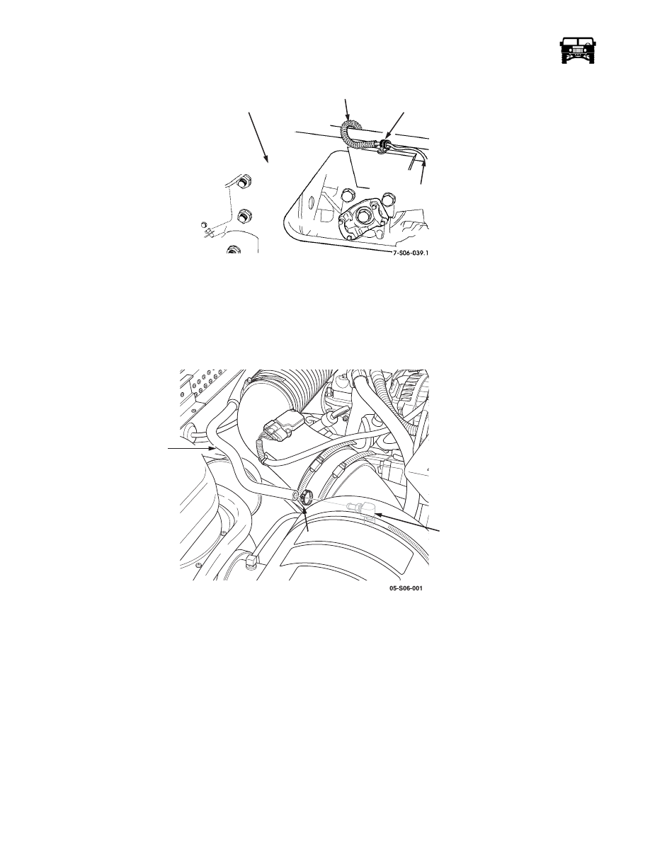
AIR INTAKE LINE REPLACEMENT

Removal

1.

Raise and secure the hood.

2.

Loosen the hose clamp and disconnect the air intake hose from the connector (Figure  6-70).

Figure 6-70:   Air Intake Hose 

3.

Loosen the clamp and disconnect the air cleaner elbow from the air horn.

4.

Remove the nut, washer, coupling, connector, and seal from the air horn.

5.

Loosen the hose clamp securing the air intake hose to the compressor fitting (Figure  6-71).

6.

Remove the air intake hose.

Cleaning and Inspection

Clean and inspect the air intake hose, elbow, coupling assembly and seal. Check for leaks, cracks, and stripped threads.

CAUTION: Do not allow sealant into the air system. Sealant will damage the CTIS components.

Installation

1.

Connect the air intake hose to the compressor fitting and secure with the hose clamp (Figure  6-71).

2.

Install the seal, coupling, washer, nut, and connector to the air horn(Figure  6-70).

AIR LINE TO

REAR

 RIGHT REAR WHEEL

AIR LINE

TO TEE

CROSSMEMBER

CLAMP

CLAMP

CONNECTOR

AIR

INTAKE

HOSE

______________

 Wheels and Tires/Central Tire Inflation System (CTIS)  6-63

5745804

3.

Connect the air cleaner elbow to the air horn and secure with the clamp.

4.

Connect the air intake hose to the air horn connector and secure with the hose clamp.

5.

Lower and secure the hood.

Figure 6-71:   Air Intake Hose to Fitting

QUICK-DISCONNECT VALVE AND TUBE REPLACEMENT

WARNING:  The CTIS components are subject to high air pressure. Always relieve the air pressure before loosen-
ing or removing air system components by disconnecting quick-disconnect valve assemblies. Failure to follow this
warning may result in serious injury.

NOTE: The replacement of all four quick-disconnect valves and tube assemblies is identical.

Removal

1.

Raise and support the vehicle.

2.

Isolate the quick-disconnect valve of the wheel being serviced and the match on the other side of the vehicle (Figure  6-74).

3.

Disconnect the compression nut and separate the tube from the quick-disconnect valve.

CAUTION: Do not force apart the quick-disconnect valve. The quick-disconnect valve is a one-piece component. Damage to the
quick-disconnect valve will result if forced apart.

4.

Remove the quick-disconnect valve from the spindle.

5.

Disconnect the compression nut from the threaded connector, then remove the nut and sleeve assembly. 

6.

Remove the threaded connector.

Cleaning and Inspection

Clean and inspect the tube and the quick-disconnect valve. Check for leaks, stripped threads, and cracks. Replace the defective
parts.

Installation

CAUTION: Do not allow sealant into the air system. Sealant will damage the CTIS components.

CLAMP

FITTING

AIR INTAKE

HOSE

12-1-05

6-64

Wheels and Tires/Central Tire Inflation System (CTIS)

_______________

NOTE: Apply sealant to the threads prior to installation.

1.

Install the quick-disconnect valve into the spindle (Figure  6-74).

2.

Install the threaded connector.

3.

Install the compression nut on the tube and connect the tube to the quick-disconnect valve.

4.

Install the compression nut on tube and connect the tube to the threaded connector.

5.

Reactivate the quick-disconnect fittings on both wheels.

6.

Adjust the air pressure in the tires as needed.

7.

Lower the vehicle.

Figure 6-72:   Quick-Disconnect Valve and Tube Replacement

TUBE CONNECTION SHIELD REPLACEMENT

NOTE: This procedure applies to all of the tube connection shields.

Removal

Remove the two bolts, washers, shield and two washers from the steering arm cover (Figure  6-73).

Cleaning and Inspection

Clean and inspect the shield and mounting hardware. Check for cracks and stripped threads. Replace the defective parts.

02-S06-001

QUICK-

DISCONNECT

VALVE

TUBE

COMPRESSION

NUTS

THREADED

CONNECTOR

12-1-05

______________

 Wheels and Tires/Central Tire Inflation System (CTIS)  6-65

5745804

Figure 6-73:   Rear Tube Connection Shield

Installation

Install the shield on the steering arm cover with two washers, bolts and two washers. Tighten the bolts to 75 lb-ft (102 N•m) (Fig-
ure  6-73).

Figure 6-74:   Line Connection at the Steering Arm Cover

SPINDLE EXTENSION AND SEAL REPLACEMENT

Removal

1.

Remove the braided CTIS hose from the 45° line fitting and remove the line fitting from the steering arm cover (Figure  6-74).

2.

Remove the tie rod end from the steering arm cover (Refer to section 9).

3.

Remove the tube connection shield (Refer to section 6).

4.

Remove the remaining two bolts, washers and the steering arm cover from the geared hub (Figure  6-75).

5.

Remove the retaining ring and seal from the steering arm cover.

STEERING

ARM COVER

SHIELD

01-S06-007

STEERING

ARM COVER

BRAIDED

HOSE

45° LINE 

FITTING

12-1-05


Content   ..  226  227  228  229   ..